Titanium sponge, zirconium sponge energy-saving reaction furnace

A technology of sponge zirconium and sponge titanium, which is applied in the field of sponge titanium and sponge zirconium production, can solve the problems of reducing Ticl4 feeding speed, product grade decline, and high labor intensity, so as to reduce labor intensity of workers, increase vacuuming speed, and eliminate safety hazards. hidden effect

Inactive Publication Date: 2015-07-08
JIANGSU XINHUI TI ZR EQUIP CO LTD
View PDF7 Cites 4 Cited by
  • Summary
  • Abstract
  • Description
  • Claims
  • Application Information

AI Technical Summary

Problems solved by technology

[0005] 1. Slow heat dissipation speed and low feeding speed: the reduction process of TiCl4 is carried out in a multi-phase coexistence system of solid, liquid and gas containing Ti, TiCl2, TiCl3, TiCl4, Mg, MgCl2, and it is also an exothermic reaction. In order to maintain Normal temperature, to prevent the formation of titanium-iron alloy, good heat dissipation must be carried out, and this method limits the reduction reaction rate and reduces the feeding rate of Ticl4 (average material rate 280-320kg / h). The reduction cycle is long and the production cost is the highest. High, but also restricts the large-scale equipment
[0006] 2. The temperature of the reaction liquid surface is not easy to control: it is easy to cause overheating or partial overheating in the production process, and the temperature exceeds 1085°C to reach the lowest eutectic point of ferro-titanium to form ferro-titanium sponge.
[0007] 3. There are potential safety hazards due to high labor intensity: During the production process, workers have to climb up to 3-4 meters on the platform outside the furnace wall to manually open or close all the blind plates of the air ducts in and out. The entire operation process takes 1-1.5 hours, and the working environment is harsh. The operating area of ​​the working platform is narrow and the ambient temperature can reach 60°C, which is prone to accidents such as heat stroke and high temperature burns

Method used


Image

  • Titanium sponge, zirconium sponge energy-saving reaction furnace
  • Titanium sponge, zirconium sponge energy-saving reaction furnace

Examples


Embodiment Construction

[0019] The preferred technical solutions of the present invention will be described in detail below in conjunction with the accompanying drawings.

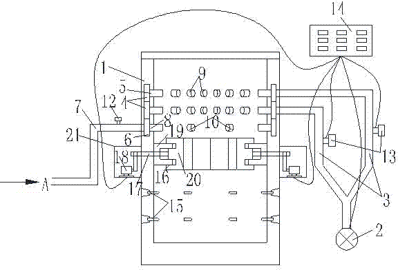
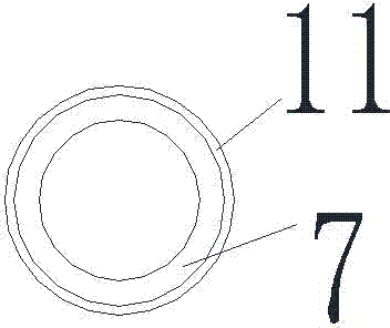
[0020] As shown in the figure, the titanium sponge and zirconium sponge energy-saving reaction furnace of the present invention includes a furnace body 1, a forced ventilation system is arranged on the upper end of the furnace body 1, and a heat-insulating vacuum energy-saving system is arranged below the forced ventilation system. The forced ventilation system includes a frequency conversion fan 2, an air inlet pipe 3, and an annular wind collection belt 4. At least two of the annular air collection belts 4 are arranged in parallel up and down, and are respectively arranged inside the side wall of the furnace body 1. The outer sides of the annular wind collecting belts 4 are respectively connected to the frequency conversion fan 2 through the air inlet pipe 3, and an air inlet 5 is uniformly arranged on the inner side of each of t...


PUM


Abstract

The invention discloses a titanium sponge, zirconium sponge energy-saving reaction furnace which comprises a furnace body, wherein a forced ventilation system is arranged at the upper end of the furnace body; a thermal insulation vacuum energy-saving system is arranged below the forced ventilation system; the forced ventilation system comprises a frequency conversion draught fan, a blast pipe and annular wind collecting belts; the annular wind collecting belts are arranged at the upper side and the lower side in a parallel mode at least and are respectively arranged inside the side wall of the furnace body; the outer side of each annular wind collecting belt is connected with the frequency conversion draught fan through the blast pipe, and an exhaust annular wind collecting belt for exhaust function is also arranged, the outer side of the exhaust annular wind collecting belt is connected with a wind collecting pipeline, and exhaust outlets are formed in the inner side of the exhaust annular wind collecting belt. The titanium sponge, zirconium sponge energy-saving reaction furnace is that the forced ventilation system is provided with the annular wind collecting belt and the exhaust annular wind collecting belt, so that inlet air and the outlet air are smooth under the power of the frequency conversion draught fan.

Description

technical field [0001] The invention relates to the technical field of sponge titanium and sponge zirconium production, in particular to an energy-saving reaction furnace for sponge titanium and sponge zirconium. Background technique [0002] At present, the smelting of sponge titanium adopts the Krall method to produce products. Foreign countries mainly adopt molten salt chlorination, I-type reheating furnace technology, boiling chlorination and inverted U-type reheating furnace technology to produce sponge titanium, while in China, upper-row magnesium chloride type I and inverted U small reheating furnace technologies are mainly used. With the development of my country's titanium sponge production technology and the continuous improvement of the production process, the smelting furnace is also becoming larger in order to increase production capacity and save costs, and the output of a single furnace is continuously increasing. Since 2009, with the continuous decline of...

Claims


Application Information

Patent Timeline
Patent Type & Authority Applications(China)
IPC IPC(8): F27B17/00F27D9/00C22B34/12C22B34/14
Inventor 王国新
Owner JIANGSU XINHUI TI ZR EQUIP CO LTD
Why Eureka
Try Eureka