Calibration system and calibration method for optical beam orientation

A azimuth calibration and calibration method technology, applied in optics, optical components, instruments, etc., can solve the problems of inability to achieve optical path calibration or recovery, restricting laser application, high cost, etc., to achieve fast and accurate optical path recovery, optical path simplicity, adjustment The effect of improved accuracy

Active Publication Date: 2015-07-08
GUANGZHOU UNIVERSITY
View PDF7 Cites 14 Cited by
  • Summary
  • Abstract
  • Description
  • Claims
  • Application Information

AI Technical Summary

Problems solved by technology

In the existing technical solutions for beam orientation calibration, precision and convenience cannot be achieved at the same time. Although complex optical systems are accurate, they usually cannot quickly and easily calibrate or restore the opti

Method used


Image

  • Calibration system and calibration method for optical beam orientation
  • Calibration system and calibration method for optical beam orientation
  • Calibration system and calibration method for optical beam orientation

Examples


Example Embodiment

[0053] Example one:

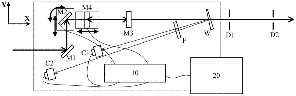
[0054] The beam orientation calibration system of this embodiment includes a first optical mirror, a second optical mirror, a third optical mirror, a fourth optical mirror, and an optical wedge. After the light beam is reflected by the first optical mirror and the second optical mirror successively, Passing from above or below the fourth optical mirror, reflected by the third optical mirror and the fourth optical mirror, and then shot from below or above the third optical mirror to the optical wedge, the two reflecting surfaces of the optical wedge are inclined to the direction of the incident beam ; Includes two light receiving devices for receiving the light beams reflected by the two reflective surfaces of the wedge; the second optical mirror is a tunable optical mirror, which can reciprocate toward the side of the light beam incident on the second optical mirror The fourth optical mirror can be translated and can be rotated in a horizontal plane; the fou...

Example Embodiment

[0056] Embodiment two:

[0057] Such as figure 1 with figure 2 As shown, in the beam orientation calibration system of this embodiment, the optical mirror adopts mirrors, including a first mirror M1, a second mirror M2, a third mirror M3, and a fourth mirror M4, and an optical wedge is used. W is used as a light splitting element, and the two light receiving devices adopt two CMOS detectors C1 and C2 for receiving light beams reflected by the two reflective surfaces of the optical wedge. An attenuator F is selectively placed in the reflected light path of the optical wedge W to control the light intensity entering the detectors C1 and C2 to avoid receiving saturation.

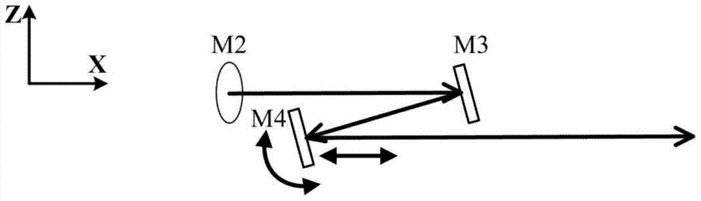
[0058] The first mirror M1 and the third mirror M3 are fixed mirrors, the second mirror M2 and the fourth mirror M4 are adjustable mirrors, and the second mirror M2 can rotate in the XY plane and can be along the Y direction Translation, the fourth mirror M4 can rotate in the XZ plane and can translate along the ...

Example Embodiment

[0068] Example three:

[0069] The third embodiment is a method for calibrating the beam position, and the second embodiment can be combined with the third embodiment to become a more preferred implementation.

[0070] The method for calibrating the beam orientation of the third embodiment includes a first optical mirror, a second optical mirror, a third optical mirror, a fourth optical mirror, an optical wedge, a light receiving device, and a controller, and the method includes the following steps:

[0071] A. After the light beam is reflected by the first optical mirror and the second optical mirror, it passes above or below the fourth optical mirror, and is reflected by the third optical mirror and the fourth optical mirror from below or above the third optical mirror When it hits the optical wedge, the light beams reflected by the two reflective surfaces of the optical wedge are received by the light receiving device;

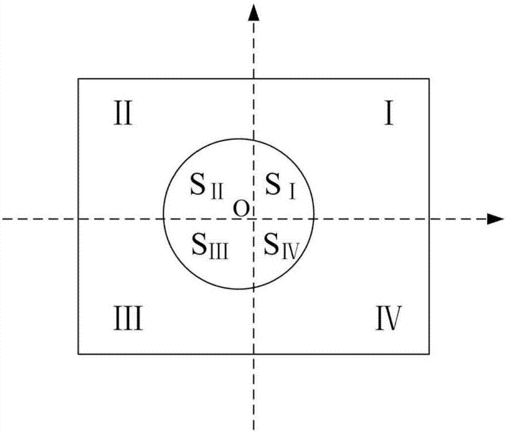
[0072] B. The light receiving device detects the offset infor...


PUM


Abstract

The invention discloses a calibration system for optical beam orientation. The calibration system comprises a first optical lens, a second optical lens, a third optical lens, a fourth optical lens, an optical wedge and two optical receiving devices; an optical beam is reflected by the first optical lens and the second optical lens in sequence and passes above or below the fourth optical lens, after the optical beam is reflected by the third optical lens and the fourth optical lens, the optical beam passes above or below the third optical lens and then shines to the optical wedge, and two reflecting surfaces of the optical wedge incline to the direction of incident light beams; the optical receiving devices are used for receiving the optical beam reflected by the two reflecting surfaces of the optical wedge, and the second optical lens and the fourth optical lens are adjustable optical lenses. The invention further discloses a calibration method of the calibration system. The calibration system and the calibration method have automatic real-time calibration functions for the optical beam orientation, and the functions can serve as front-end systems for all kinds of laser precise application systems. The calibration system can record the state of a normal work optical path, and the quick and precise optical path recovery can be achieved.

Description

Technical field [0001] The invention belongs to the field of optoelectronic technology, and specifically relates to a beam orientation calibration system and a calibration method thereof. Background technique [0002] In the application fields of laser technology, such as free space optical communication, laser precision measurement, laser biomedicine and other application fields, there are higher requirements for the direction and azimuth stability of the laser beam. [0003] For precision laser applications, due to the temperature deformation of the laser cavity, the instability of the optical components on the transmission path, and the influence of various environmental disturbance factors, the laser beam will always show a slight azimuth shift, including angle shift and parallel shift shift. When the offset is large, it will seriously affect the stability of the subsequent system. [0004] In addition, in actual work, it is often necessary to restore the optical path of the op...

Claims


Application Information

Patent Timeline
IPC IPC(8): G02B27/30
CPCG02B27/30
Inventor 陈志峰欧叙文贺巍威黎达宇钟永贤
Owner GUANGZHOU UNIVERSITY
Why Eureka
Try Eureka