Micro-strip rectification antenna based on WIFI frequency band

A rectenna and microstrip technology, which is applied to the structural connection of the antenna and the antenna grounding switch, and the devices that make the antenna work in different frequency bands at the same time, can solve the problems of large size, high production cost, and low conversion efficiency of the rectenna. The effect of high receiving efficiency, low cost and simple structure

Inactive Publication Date: 2015-07-08
SYSU CMU SHUNDE INT JOINT RES INST +1
View PDF3 Cites 19 Cited by
  • Summary
  • Abstract
  • Description
  • Claims
  • Application Information

AI Technical Summary

Problems solved by technology

[0004] However, due to the shortcomings of traditional rectennas such as large volume, high quality, high production cost, and low conversion efficiency, their use in many occasions is limited.

Method used


Image

  • Micro-strip rectification antenna based on WIFI frequency band
  • Micro-strip rectification antenna based on WIFI frequency band
  • Micro-strip rectification antenna based on WIFI frequency band

Examples


Embodiment 1

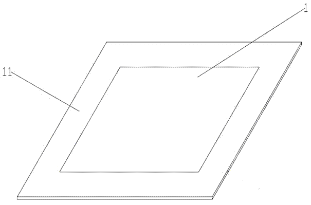
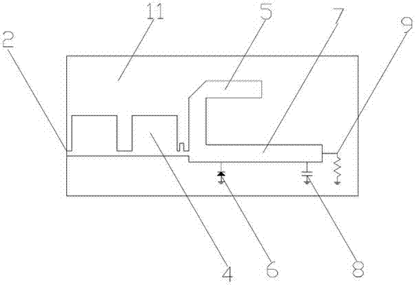
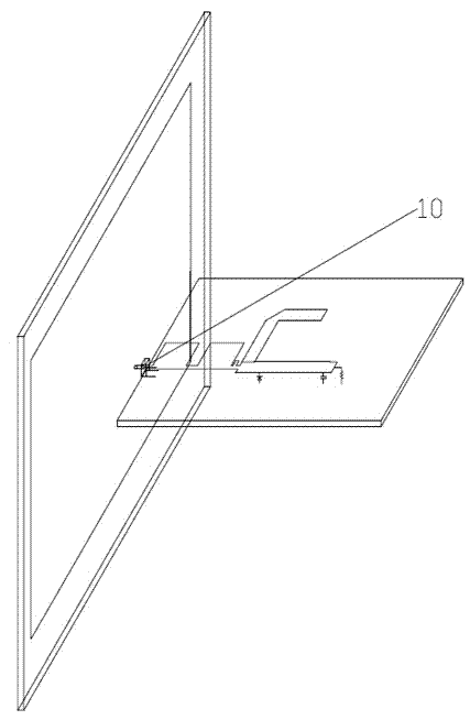
[0027] Such as Figure 1-3 As shown, a microstrip rectifying antenna based on the WIFI frequency band includes a microstrip receiving antenna 1 and a microstrip rectifying circuit 2, the microstrip receiving antenna 1 is a coaxial feeding rectangular microstrip antenna, the microstrip receiving antenna 1 and the microstrip The rectifier circuit 2 adopts printed circuit, the microstrip receiving antenna 1 and the microstrip rectifying circuit 2 are made on two PTFE double-sided copper-clad substrates 11 respectively, and the microstrip receiving antenna 1 and the microstrip rectifying circuit 2 adopt SMA Head 10 to connect.

[0028] In this embodiment, both the microstrip antenna 1 and the microstrip rectification part 2 are implemented by microstrip circuits, which are respectively fabricated on the substrate 11 of a polytetrafluoroethylene double-sided copper-clad laminate, the substrate thickness is 0.8mm, and the dielectric constant is 2.55. , the loss tangent value is les...


PUM


Abstract

The invention provides a micro-strip rectification antenna based on a WIFI frequency band. The micro-strip rectification antenna based on the WIFI frequency band comprises a micro-strip receiving antenna and a micro-strip rectification circuit, wherein the micro-strip receiving antenna is a coaxial feed rectangular micro-strip antenna, and the micro-strip receiving antenna and the micro-strip rectification circuit both adopt printing circuits and manufactured on two Teflon double-sided copper-coated substrates respectively and connected through an SMA head. The micro-strip rectification antenna based on the WIFI frequency band is produced in batches through the printing circuit technology, is low in cost, is easy to realize, is based on the 2.45GHZ and 5.8GHz WIFI frequency bands, is wide in application range, is easy to popularize and has the advantages of being high in gain and large in receiving efficiency.

Description

technical field [0001] The present invention relates to the field of wireless energy transmission, and more specifically, relates to a microstrip rectenna based on a WIFI frequency band. Background technique [0002] Microwave Power Transmission (MPT: Microwave Power Transmission) refers to a new transmission method to achieve energy transmission in vacuum or atmosphere without any other transmission lines or waveguides. At the end of the 19th century, the American scientist Nikola Tesla first proposed the concept of MPT. In the 1960s, MPT technology was first used in high-power applications, including power generation in space, power transmission from the ground to aircraft such as satellites and aircraft, military directed energy weapons, and interstellar exploration. However, because the overall conversion efficiency of the MPT system is not high, and the high-power microwave electromagnetic field has a great impact on the ecological environment and biological safety, th...

Claims


Application Information

Patent Timeline
Patent Type & Authority Applications(China)
IPC IPC(8): H01Q1/38H01Q1/50H01Q5/20
Inventor 谭洪舟张全琪严曙辉詹茜
Owner SYSU CMU SHUNDE INT JOINT RES INST
Why Eureka
Try Eureka