High-speed laser device driving circuit

A driving circuit and laser technology, which is applied in the field of optical communication systems, can solve the problems of difficult design of high-frequency impedance matching of laser driving circuits, etc.

Inactive Publication Date: 2015-07-08
HUBEI UNIV OF TECH
View PDF5 Cites 11 Cited by
  • Summary
  • Abstract
  • Description
  • Claims
  • Application Information

AI Technical Summary

Problems solved by technology

However, at high rates (such as 10Gbps and above), due to the high-speed and high-current driving capability requirements of the laser drive circuit and the high-frequency impedance matching

Method used


Image

  • High-speed laser device driving circuit
  • High-speed laser device driving circuit
  • High-speed laser device driving circuit

Examples


Embodiment Construction

[0027] The technical solution of the present invention will be specifically described below in conjunction with the accompanying drawings and embodiments.

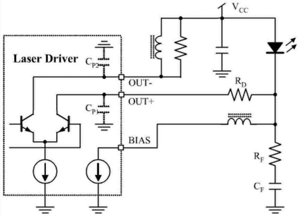
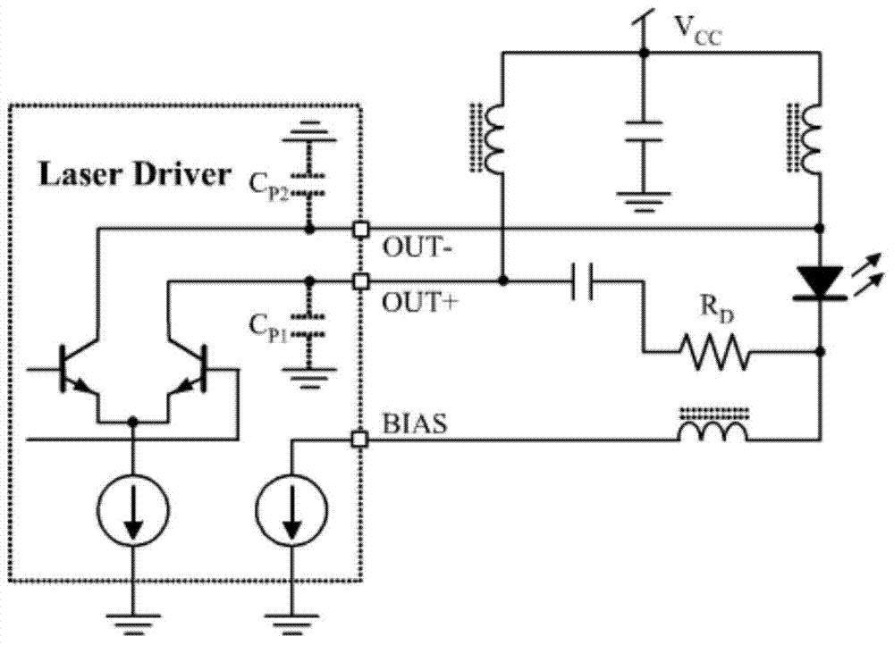
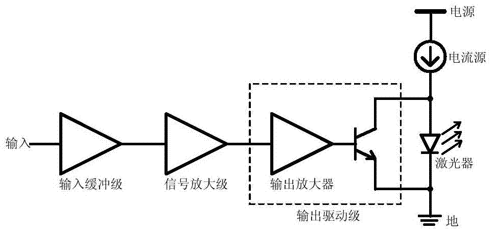
[0028] The present invention proposes a new direct modulation drive circuit structure, the basic principle of which is to change the traditional direct modulation mode of the laser realized in the form of current source series into a direct modulation mode of controlling the optical power of the laser in the form of high-speed switching, that is, the working of the laser The current is provided by the same current source, and the magnitude of the current flowing through the laser and its output power can be quickly adjusted by controlling the opening and closing of the transistor, thereby realizing direct modulation of the high-speed laser.

[0029] A high-speed laser drive circuit provided by the present invention includes:

[0030] An input buffer stage whose function is to equalize and compensate the input signal;

[0...


PUM


Abstract

The invention provides a high-speed laser device driving circuit which involves an input buffer stage, a signal amplification stage, an output driving stage, a laser device current source and a directly modulated laser device. The output driving stage comprises an output amplifier and a transistor, the output end of the input buffer stage is connected with the input end of the signal amplification stage, the output end of the signal amplification stage is connected with the input end of the output amplifier, the output end of the output amplifier is connected with the transistor, the transistor is a BJT transistor or an MOSFET transistor, only one laser device current source is arranged, and the laser device current source is connected between a power supply and the anode of the directly modulated laser device or connected between the cathode of the directly modulated laser device and the ground. The high-speed laser device driving circuit can be used for directly driving high-speed distributed feedback laser devices and others, and the design difficulty of an existing high-speed directly modulated laser device driving circuit is reduced.

Description

technical field [0001] The invention belongs to the field of optical communication systems and relates to a high-speed laser drive circuit. Background technique [0002] The optical module is the basic hardware to realize the optical communication system, and the high-speed laser driver circuit is the basic component for the high-speed optical module to realize the light emission function. Compared with the electro-absorption modulation method, the direct modulation method can greatly reduce the cost of the optical transmitter, thereby significantly reducing the cost of the optical module and the system. At present, the direct modulation drive circuit for directly modulated lasers (for example, distributed feedback laser, Distributed Feedback Laser, DFB) generally divides the current of the laser into two parts, the bias current and the modulation current, and generates them separately for the laser. Among them, the bias current is used to provide the current required when ...

Claims


Application Information

Patent Timeline
IPC IPC(8): H01S5/042
Inventor 赵楠武明虎熊炜周先军刘聪朱莉曾春艳
Owner HUBEI UNIV OF TECH
Why Eureka
Try Eureka