
Method for eliminating vibration of PWM powered brushless direct current motor through frequency calculation

A brush DC motor, frequency calculation technology, applied in the direction of electrical components, electromechanical devices, etc., can solve the problems of not considering the influence of cogging shape, inaccurate calculation of each harmonic amplitude of flux density, inaccurate calculation of motor vibration frequency, etc. , to achieve the effect of improving the success rate, improving accuracy, and shortening the development and trial production cycle

Active Publication Date: 2015-07-08
SHANGHAI MOTOR SYST ENERGY SAVING ENG TECH RES CENT +2
View PDF7 Cites 4 Cited by
  • Summary
  • Abstract
  • Description
  • Claims
  • Application Information

AI Technical Summary

Problems solved by technology

[0007] 1. The calculation method of the equivalent magnetic circuit is adopted, and the parameters such as magnetic permeability are equivalent values, and the influence of the shape of the cogging on the magnetic permeability is not considered;
[0008] 2. The magnetic density value is calculated from the magnetic potential and magnetic permeability. The air gap magnetic density calculation result is an equivalent value, and the amplitude calculation of each harmonic of the magnetic density is inaccurate;
[0009] 3. Only the space harmonics of the air-gap flux density generated by the stator and rotor are considered, and the change of the air-gap flux density with time during PWM power supply is not considered
[0010] The above defects make the calculation of motor vibration frequency under PWM power supply inaccurate

Method used

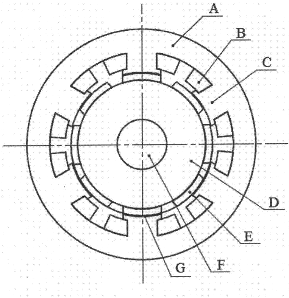
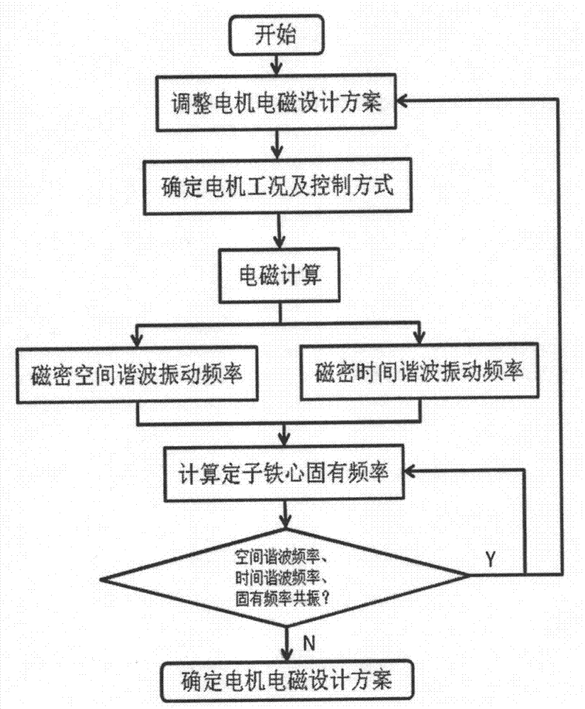
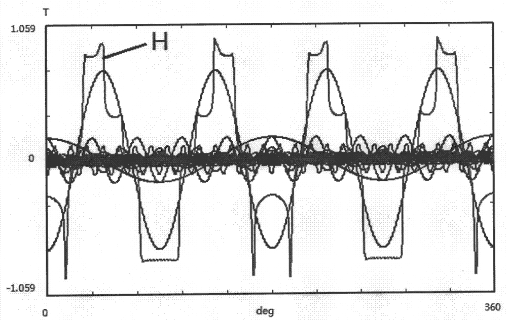

Image

  • Method for eliminating vibration of PWM powered brushless direct current motor through frequency calculation
  • Method for eliminating vibration of PWM powered brushless direct current motor through frequency calculation
  • Method for eliminating vibration of PWM powered brushless direct current motor through frequency calculation

Examples


Embodiment Construction

[0033] The train of thought of the method for suppressing the vibration of the PWM-powered brushless DC motor provided by the present invention through frequency calculation is: for a motor with a preliminarily designed electromagnetic scheme, the space harmonic distribution of the air-gap flux density is first calculated, and then within a commutation period Calculate the time harmonic change of the air gap magnetic density and compare it with the natural vibration frequency of the motor core. If the frequency is close, that is, in the resonance zone, resonance will occur. It is necessary to optimize the electromagnetic design scheme of the motor and recalculate each frequency. The vibrations generated up to space harmonic flux density and time harmonic flux density do not resonate with the iron core.

[0034] The frequency range of the resonance area is related to the equivalent stiffness and mass of the stator core. In the calculation of the motor frequency, the resonance ar...


PUM


Abstract

The invention provides a method for eliminating vibration of a PWM powered brushless direct current motor through frequency calculation. For the motor preliminarily designed in a electromagnetic scheme, spatial harmonic distribution of air gap flux density is firstly calculated, then the time harmonic wave change of the air gap flux density is calculated within a commutation period and is compared with the inherent vibration frequency of a motor iron core, and if the frequencies are similar, resonance is produced, the electromagnetic design scheme of the motor is needed to be optimized, and the frequencies are re-calculated till the vibrations produced by spatial harmonic flux density and harmonic wave flux density are not resonant with the iron core. The space and time changes of flux density causing motor vibration under the operating working condition of the motor are fully considered in the method, the accuracy of motor vibration calculation in a motor product development phase is improved, accordingly the success rate of motor design is improved, a development and trial-manufacturing period of the motor is shortened, and non-renewable resources including copper, iron, aluminum and the like are effectively saved.

Description

technical field [0001] The invention relates to a method for suppressing motor vibration by calculating the motor stator core vibration frequency caused by air-gap flux density harmonics for a brushless DC motor powered by PWM (pulse width modulation mode), and belongs to the technical field of DC motors. Background technique [0002] The vibration sources of brushless DC motor vibration can be divided into three types: electromagnetic force, aerodynamic force and mechanical structure. These three vibration sources have large differences in vibration frequency, and the noise generated by vibration is easy to distinguish. The vibration generated by aerodynamic force and mechanical structure as the vibration source is mechanical vibration, which can be optimized through the design of the motor structure, such as improving the motor ventilation structure, changing the geometric dimensions of the motor structural parts, etc., and the vibration generated by the electromagnetic for...

Claims


Application Information

Patent Timeline
Patent Type & Authority Applications(China)
IPC IPC(8): H02K29/03
Inventor 王鸿鹄姚丙雷张宝强顾德军金晶
Owner SHANGHAI MOTOR SYST ENERGY SAVING ENG TECH RES CENT
Learn More