Mobile terminal

A mobile terminal and output technology, applied in transmission systems, inductors, instruments, etc., can solve the problems of increasing product thickness, affecting product portability, and low heat dissipation efficiency of mobile terminals.

Inactive Publication Date: 2015-07-08
FUTAIHUA PRECISION ELECTRONICS ZHENGZHOU +1
View PDF3 Cites 11 Cited by
  • Summary
  • Abstract
  • Description
  • Claims
  • Application Information

AI Technical Summary

Problems solved by technology

However, the heat dissipation efficiency of this kind of mobile terminal is low, and because the heat dissipation layer made of heat-conducting materials such as copper foil or graphite is arranged on the housing, the thickness of the product will be increased accordingly and the portability of the product will be affected.

Method used


Image

  • Mobile terminal
  • Mobile terminal
  • Mobile terminal

Examples


Embodiment Construction

[0017] The mobile terminal of the present invention will be further described in detail below with reference to the drawings and specific implementation methods.

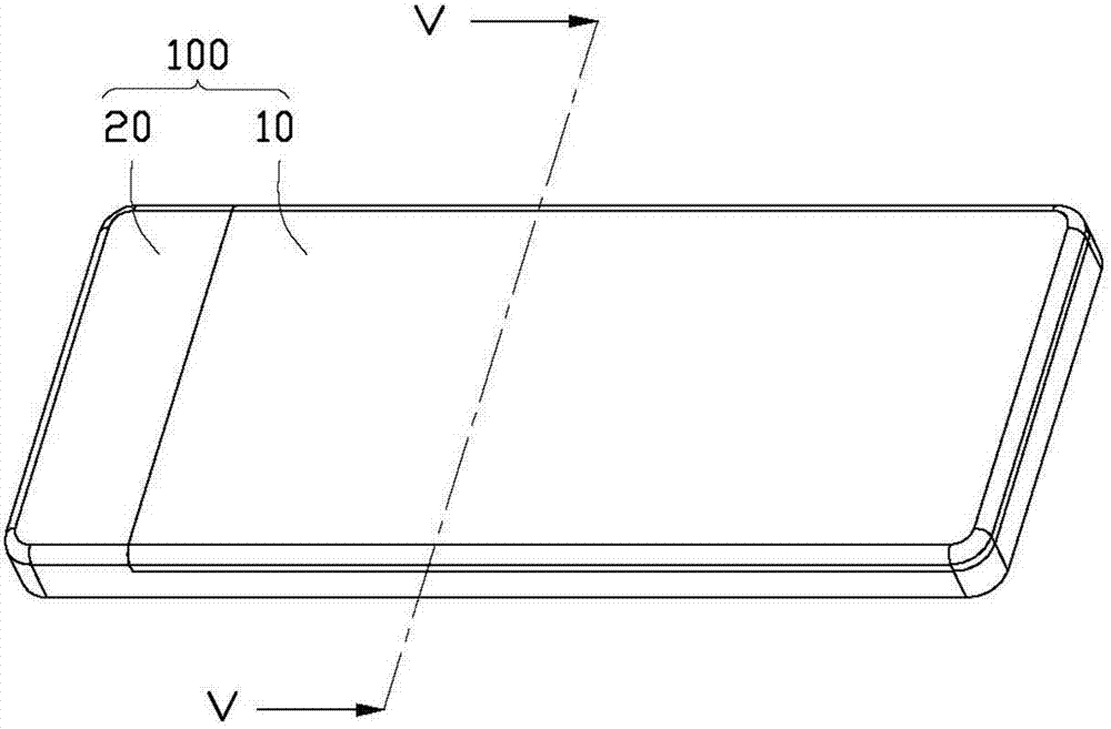
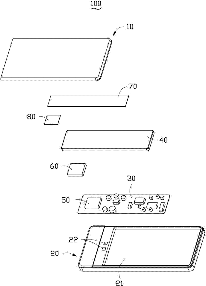
[0018] see figure 1 and figure 2 , The mobile terminal 100 provided by the preferred embodiment of the present invention includes a casing 10 and a body 20 matched with the casing 10 . The casing 10 and the body 20 are superimposed to form a closed receiving space, and combined into a substantially rectangular whole.

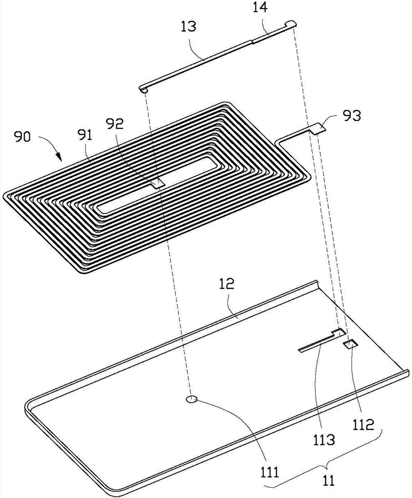
[0019] The mobile terminal 100 also includes a motherboard 30 accommodated between the casing 10 and the body 20, a battery 40, a chip 50, and an induction coil 90 embedded in the casing 10 ( Figure 5 shown).

[0020] In this embodiment, the battery 40 and the chip 50 are electronic components that generate a lot of heat. Correspondingly, the area where the electronic component that generates a lot of heat or its adjacent area is a high heat generation area of ​​the mobile terminal 100 . But not...


PUM


Abstract

An electrically powered portable device powered remotely and wirelessly includes a cover, a main body engaged with the cover, and an induction coil positioned inside the cover. The two ends of the induction coil are a first output terminal and second output terminal The first output terminal and second output terminal lead to a surface of the cover, where an induction current from the induction coil is outputted.

Description

technical field [0001] The present invention relates to an electronic product, in particular to a mobile terminal. Background technique [0002] With the rapid development of electronic products, they are facing more and more challenges in electrical performance. At the same time, the consumer market has put forward higher requirements for the comprehensive performance of electronic products, especially posing greater challenges to the waterproof performance and heat dissipation performance of mobile terminals. [0003] Traditional mobile terminals often need to be charged with a charging interface connected to the charger. However, as the charging times increase, the non-sealed design of the charging structure is more likely to cause water in the external environment to enter the mobile terminal through the charging interface, which will reduce the Waterproof performance of mobile terminals. The mobile terminal wireless charging technology based on the principle of electr...

Claims


Application Information

Patent Timeline
Patent Type & Authority Applications(China)
IPC IPC(8): H05K5/00H05K7/20
CPCH02J7/025G06F1/16H05K5/03H05K5/0247H02J5/005H01F38/14H04B5/0037H04B5/0075G06F1/1635G06F1/20H02J50/005H02J50/10H02J50/70
Inventor 章绍汉
Owner FUTAIHUA PRECISION ELECTRONICS ZHENGZHOU
Why Eureka
Try Eureka