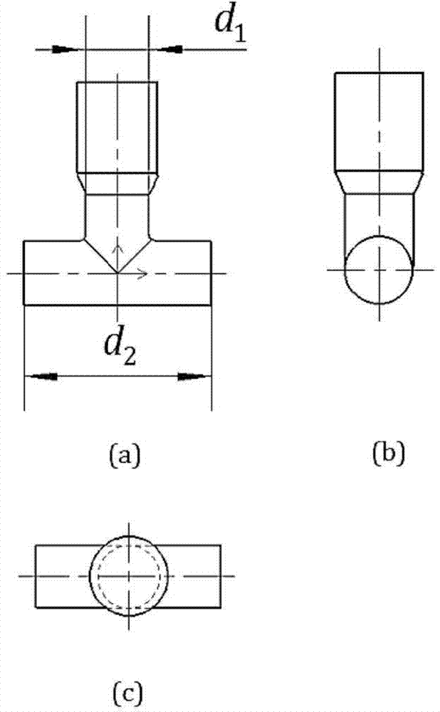
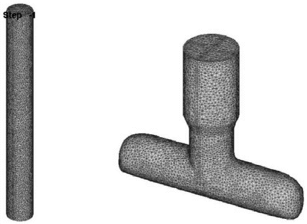
T type part vertical multiple process step extrusion die and forming technology thereof
An extrusion die and multi-step technology, which is applied in the direction of manufacturing tools, metal processing equipment, forging/pressing/hammer devices, etc., can solve the problems of frictional resistance surface defects, unfavorable T-shaped parts forming, and difficulty in mass production. Achieve the effects of forming process stability, improving production efficiency, and improving the mechanical properties of workpieces
- Summary
- Abstract
- Description
- Claims
- Application Information
AI Technical Summary
Problems solved by technology
Method used
Image
Examples
Embodiment 1
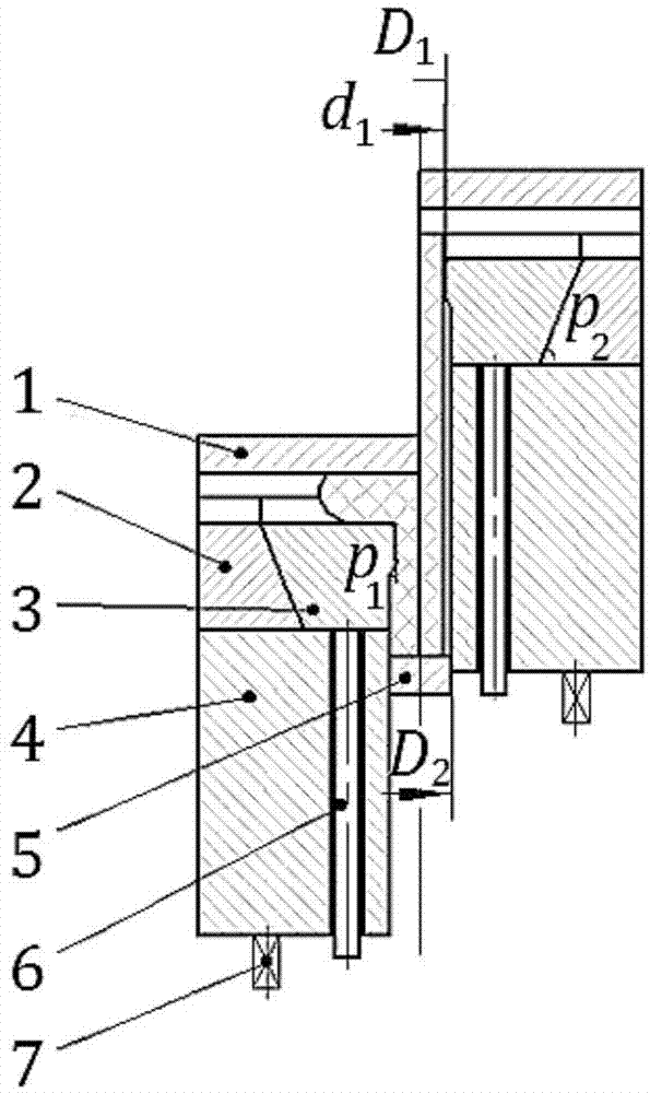
[0030] Such as image 3 As shown, this embodiment relates to an extrusion die, including: an upper die 1, a lower die 2, an inclined slider 3, a sleeve 4, a push rod 5, a push rod 6 and an elastic element 7, wherein: the upper die When mold 1, lower die 2, and inclined slider 3 are closed, a cylindrical mold cavity is formed. The sleeve 4 is controlled by the elastic element 7 to realize floating control. The concave mold is designed with a side core-pulling mechanism of the inclined slider, and the push rod 6 is set on the In the sleeve 4, the lower end is fixed on the inclined slider 3.
[0031] The diameters of the upper and lower parts of the inner side wall of the inclined slider 3 are different, and the large diameter of the upper part makes the large step of the rod part shape, and the diameter of the cavity is D 1 3.8mm, D 2 is 4.8mm, and there is a transition bevel in the middle, where the angle p 1 is 22.5°; inclined slider 3 inclined slider height h 1 =8.3mm, th...
Embodiment 2
[0038] The cavity diameter D in this example 1 3.9mm, D 2 is 4.9mm, and there is a transition bevel in the middle, where the angle p 1 is 23.5°; inclined slider 3 inclined slider height h 1 =8.3mm, the inclination angle is p 2 = 65°.
[0039] The process steps involved in this embodiment are as follows:
[0040] The first step is to use 20# steel to cut the material with bar, among which: the height of the bar is 32mm, the diameter is 3.8mm, and the diameter of the blank is d 1 0.1mm smaller in diameter;
[0041] The second step is forming. Put the cylindrical blank into the extrusion mold cavity for extrusion. The upper die, the lower die and the sleeve are pressed down by 18.5mm, so that the upper end of the workpiece is completely filled with the die cavity, and the lower end is completely filled. length to d 3 greater than d 2 =11.8mm;
[0042] The third step is unloading, the push rod drives the inclined slider to move obliquely, and the billet can be ejected by ...
Embodiment 3
[0044] The cavity diameter D in this example 1 4.0mm, D 2 is 5.0mm, and there is a transition bevel in the middle, where the angle p 1 is 24.5°; inclined slider 3 inclined slider height h 1 =8.3mm, the inclination angle is p 2 = 63°.
[0045] The process steps involved in this embodiment are as follows:
[0046] The first step is to use 15# steel for cutting with bar stock, among which: the bar stock height is 32mm, the diameter is 3.9mm, and the diameter of the blank is d 1 0.1mm smaller in diameter;
[0047] The second step is forming. Put the cylindrical blank into the extrusion mold cavity for extrusion. The upper die, the lower die and the sleeve are pressed down by 18.5mm, so that the upper end of the workpiece is completely filled with the die cavity, and the lower end is completely filled. length to d 3 greater than d 2 =11.8mm;
[0048] The third step is unloading, the push rod drives the inclined slider to move obliquely, and the billet can be ejected by the...
PUM
 Abstract
Description
Claims
Application Information
 - R&D
- Intellectual Property
- Life Sciences
- Materials
- Tech Scout
- Unparalleled Data Quality
- Higher Quality Content
- 60% Fewer Hallucinations
Browse by: Latest US Patents, China's latest patents, Technical Efficacy Thesaurus, Application Domain, Technology Topic, Popular Technical Reports.
© 2025 PatSnap. All rights reserved.Legal|Privacy policy|Modern Slavery Act Transparency Statement|Sitemap|About US| Contact US: help@patsnap.com


