

Vacuum pipe type vibration feeding machine
A vibrating feeder and vacuum tube type technology, which is applied to vibrating conveyors, conveyors, conveyor objects, etc., can solve the problems of narrow maintenance space, long time consumption, and high working environment temperature, so as to reduce the failure rate and enhance flexibility , the effect of reducing vibration
- Summary
- Abstract
- Description
- Claims
- Application Information
AI Technical Summary
Problems solved by technology
Method used
Image

Examples
Embodiment Construction
[0021] The present invention will be described in further detail below in conjunction with the accompanying drawings.
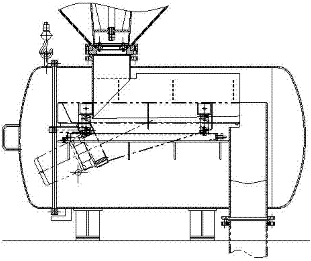
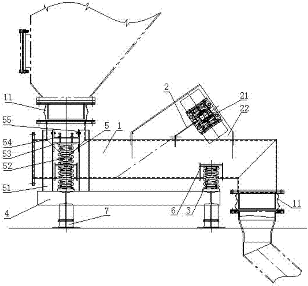
[0022] see figure 2 , a vacuum tube vibrating feeder, including a feeding tube body 1 and a vibrating device 2, the vibrating device 2 includes two eccentric vibrating motors 21 and a thrust plate 22, and the eccentric vibrating motor 21 is fixed on the thrust plate 22 by bolts , the thrust plate 22 is fixedly welded on the outer wall of the feeding pipe body 1, and the two ends of the feeding pipe body 1 are respectively the feed inlet and the discharge outlet, which are passageways for alloy materials, and the feed inlet of the feed pipe body 1 It is connected with the outlet of the silo through a flange, the outlet of the feeding pipe body 1 is connected with the inlet of the feeding chute through a flange, and the limit mechanism 5 is set on both sides of the inlet of the vacuum tube feeder, fixed Welded on the connection support frame 4, the pre-tighte...
PUM
 Abstract
Description
Claims
Application Information