U-support lead-screw washing maintaining device
A technology of screw and transmission device, which is applied in the field of U-support screw cleaning and maintenance devices, can solve problems such as the impact of secondary turnover, unsatisfactory cleaning effect, and slow cleaning speed, so as to reduce construction costs, reduce labor consumption, and save Labor and Cost Effects
- Summary
- Abstract
- Description
- Claims
- Application Information
AI Technical Summary
Problems solved by technology
Method used
Image

Examples
Embodiment 1
[0020] Embodiment 1 U support screw cleaning and maintenance device
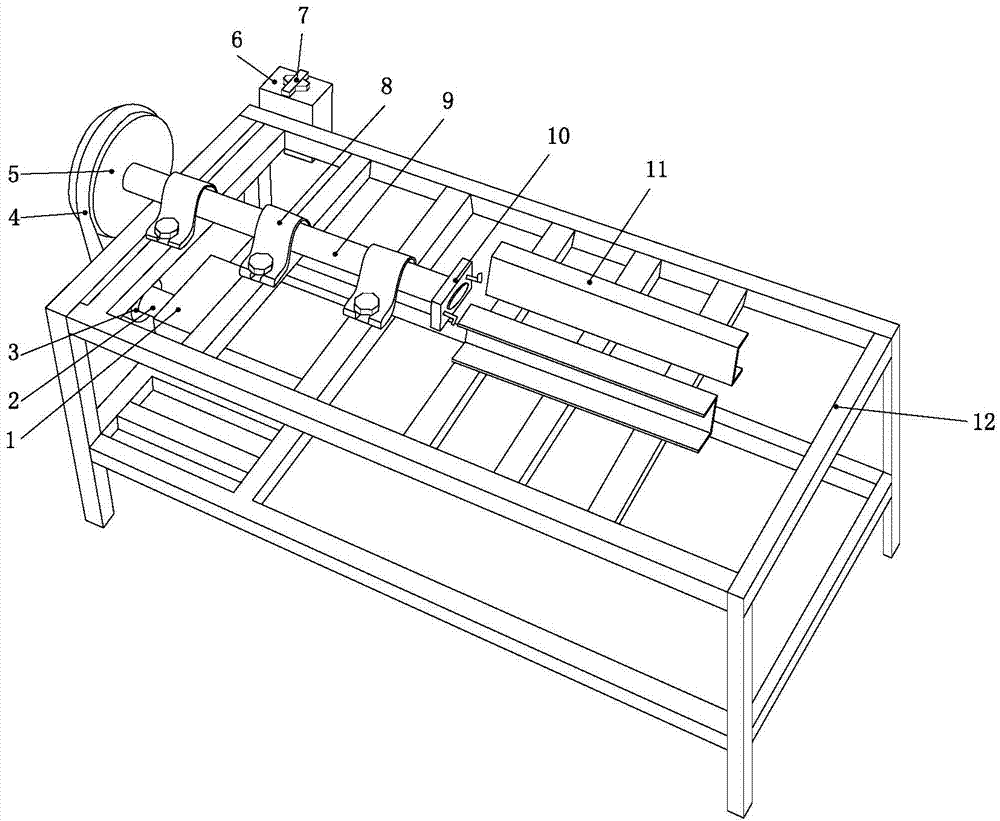
[0021] like figure 2 Shown, a kind of U support leading screw cleaning and maintenance device is made of console 12, motor 1, transmission, rotating shaft 9, chuck 10 and guide channel steel 11.
[0022] The operating table 12 is welded by 40×40 square steel, and its length, width and height are 1100×500×600cm respectively.
[0023] The transmission device is composed of pulley I3, transmission belt 4 and pulley II5.
[0024] The motor 1 is connected to the pulley I3 through the output shaft 2, the pulley I3 is connected to the pulley II5 through the transmission belt 4, and the pulley II5 is connected to the rotating shaft 9. The motor drives the rotating shaft to rotate through the transmission device.
[0025] The rotating shaft 9 is fixed on the console 12 through the bearing housing 8 .
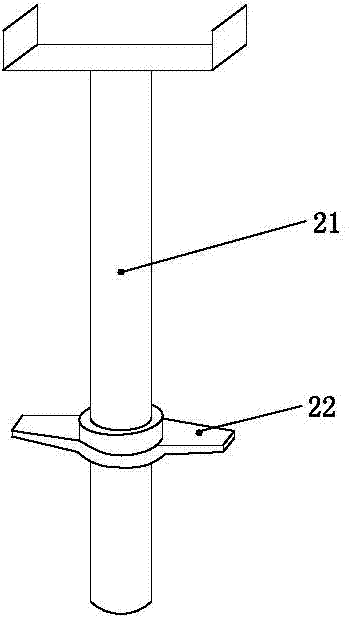
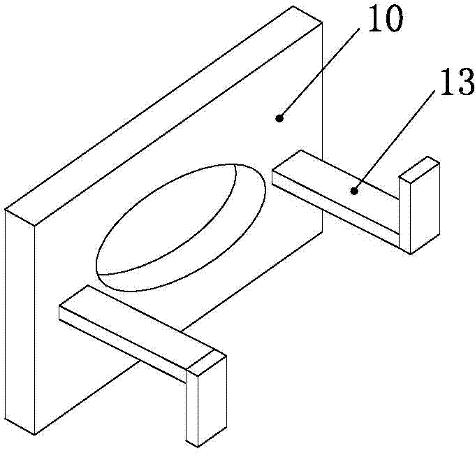
[0026] One end of rotating shaft 9 passes chuck 10 and is fixed with chuck 10, as image 3 As shown, the chuck...
Embodiment 2
[0029] Example 2 Cleaning and maintenance device for U-support screw
[0030] like Figure 4 As shown, a U-support screw cleaning and maintenance device consists of an operating table 12, a motor 1, a transmission device, a rotating shaft 9, a chuck 10, a guide channel steel 11, an oil tank 14, an oil pump 15, a nozzle 16, and a recovery funnel 17 And protective cover I19 composition.
[0031] The operating table 12 is welded by 40×40 square steel, and its length, width and height are 1100×500×600cm respectively.
[0032] The transmission device is composed of pulley I3, transmission belt 4 and pulley II5.
[0033] The motor 1 is connected to the pulley I3 through the output shaft 2, the pulley I3 is connected to the pulley II5 through the transmission belt 4, and the pulley II5 is connected to the rotating shaft 9. The motor drives the rotating shaft to rotate through the transmission device.
[0034] The rotating shaft 9 is fixed on the console 12 through the bearing hou...
Embodiment 3
[0042] Example 3 Cleaning and maintenance device for U-support screw
[0043] like Figure 5 As shown, a U-support screw cleaning and maintenance device consists of an operating table 12, a motor 1, a transmission device, a rotating shaft 9, a chuck 10, a guide channel steel 11, an oil tank 14, an oil pump 15, a nozzle pipe 16, and a recovery funnel 17 , Protective cover I19 and protective cover II20 constitute.
[0044] The operating table 12 is welded by 40×40 square steel, and its length, width and height are 1100×500×600cm respectively.
[0045] The transmission device is composed of pulley I3, transmission belt 4 and pulley II5.
[0046] The motor 1 is connected to the pulley I3 through the output shaft 2, the pulley I3 is connected to the pulley II5 through the transmission belt 4, and the pulley II5 is connected to the rotating shaft 9. The motor drives the rotating shaft to rotate through the transmission device.
[0047] The rotating shaft 9 is fixed on the consol...
PUM
 Abstract
Description
Claims
Application Information
 - R&D
- Intellectual Property
- Life Sciences
- Materials
- Tech Scout
- Unparalleled Data Quality
- Higher Quality Content
- 60% Fewer Hallucinations
Browse by: Latest US Patents, China's latest patents, Technical Efficacy Thesaurus, Application Domain, Technology Topic, Popular Technical Reports.
© 2025 PatSnap. All rights reserved.Legal|Privacy policy|Modern Slavery Act Transparency Statement|Sitemap|About US| Contact US: help@patsnap.com