
Circuit for expanding range of pulse laser short-range dynamic gain

A dynamic gain, pulsed laser technology, used in radio wave measurement systems, instruments, etc., can solve the problems of poor flexibility of the gain curve, time-consuming measurement process, and immaturity, and achieve the effect of expanding the dynamic gain range.

Inactive Publication Date: 2015-07-15
HEFEI INSTITUTES OF PHYSICAL SCIENCE - CHINESE ACAD OF SCI
View PDF3 Cites 20 Cited by
  • Summary
  • Abstract
  • Description
  • Claims
  • Application Information

AI Technical Summary

Problems solved by technology

Therefore, in the case of large changes in laser pulse echo power, the realization of high-precision ranging of vehicle-mounted lidar requires the introduction of an AGC (automatic gain control) circuit in the echo receiving circuit (Wu Wenyin 1984, Chen Xiwu et al. 1996, Li Jinduo 1997, Hou Lijuan et al. 2002, Hu Chunsheng 2005, Zhang Jian 2005, Guo Ying et al. 2010, Li Ming et al. 2011, Zhu Qi 2011), or STC (Sensitive Time Control) circuit (Xiang Shihao 2003, Liu Jiaming 2012), or using other chip technologies, but the research on this aspect is not very mature
Zhou Qiang et al. (Zhou Qiang et al. 2012) proposed a short-range gain control method using CPLD. The measurement range is 50-500 meters, but the accuracy is poor, and this method does not give the short-range gain control method less than 50 meters. Realization method; Hu Chunsheng (Hu Chunsheng 2005) proposed a method of using RC network charge and discharge to realize the control curve, and achieved gain control within 30 meters. Due to the characteristics of RC network charge and discharge performance, the flexibility of the gain curve is relatively small. Difference
Zhu (Zhu et al. 2012) proposed a method of introducing AGC into both the pre-TIA amplifier and the post-processing amplifier, and achieved an error of 3cm within the range of 5-500 meters. However, this method requires peak sampling, so The measurement process requires at least two pulse transmissions, one of which is used to collect the peak value and adjust the gain according to the peak value. The entire measurement process takes a lot of time

Method used


Image

  • Circuit for expanding range of pulse laser short-range dynamic gain
  • Circuit for expanding range of pulse laser short-range dynamic gain
  • Circuit for expanding range of pulse laser short-range dynamic gain

Examples


Embodiment Construction

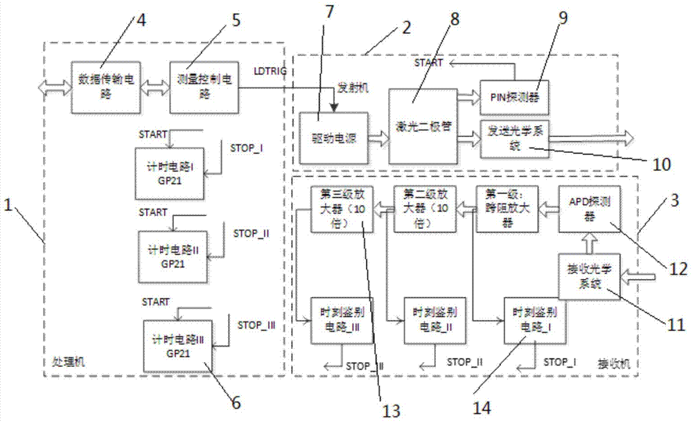
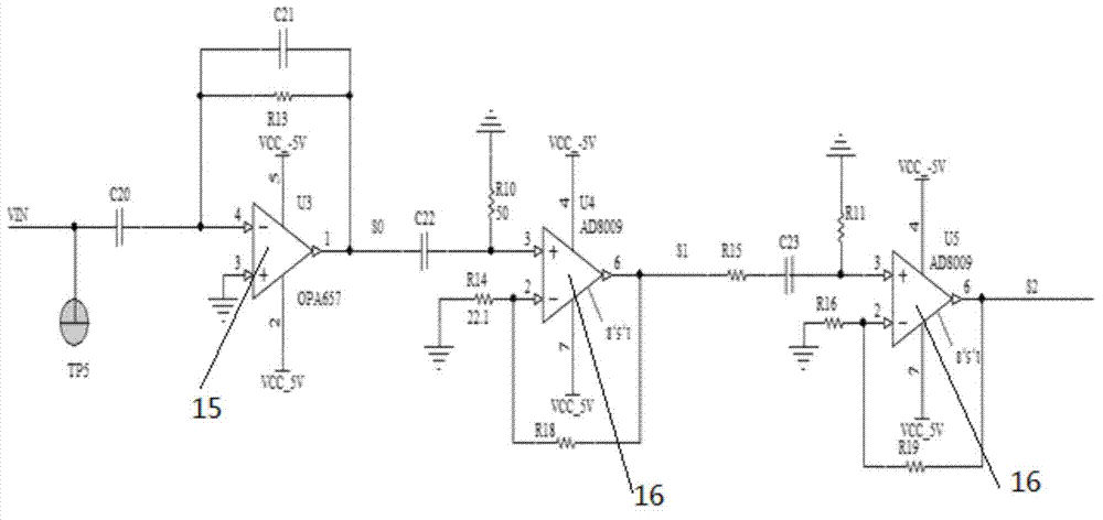
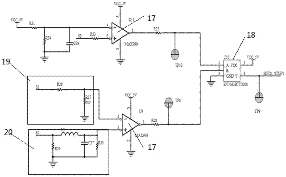
[0013] Such as figure 1 As shown, a short-range dynamic gain range circuit for extended pulsed lasers includes a processor 1, a transmitter 2 and a receiver 3, and the processor 1 includes a data transmission circuit 4, a measurement control circuit 5 and three timing Circuit 6, data transmission is carried out by FPGA between the described data transmission circuit 4 and the measurement control circuit 5, and the described transmitter 2 includes a driving power supply 7, a laser diode 8, a PIN detector 9 and an optical transmitter 10, the described The receiver 3 includes an optical receiver 11, an APD detector 12, a three-stage amplifier circuit 13 and three time discrimination circuits 14, and the measurement control circuit 5 generates a bundle of narrow pulse signals and transmits them to the drive power supply 7 , the driving power supply 7 drives the laser diode 8 to generate laser pulse signals and transmits them to the PIN detector 9 and the optical transmitter 10 res...


PUM


Abstract

The invention discloses a circuit for expanding a range of pulse laser short-range dynamic gain. When echo signals pass through a three-stage amplification circuits, voltage signals amplified at each stage are input into a time discriminator circuit; an STOP signal is generated after the discrimination of the time discriminator circuit and is input into a corresponding timing circuit formed by TDC-GP21; finally discrimination and optimization by a measurement controller formed by FPGA according to the designed Verilog HDL codes and three TDC-GP21 measurement time intervals are carried out, thereby calculating the flight distance of laser. The circuit has the advantages that the dynamic range of the laser radar short-range distance measurement is expanded, the distance measurement accuracy is improved, and the circuit is capable of controlling the laser radar short-range gain without the introduction of STC or AGC circuits.

Description

technical field [0001] The invention relates to the technical field of pulse laser measurement, in particular to a circuit for expanding the short-range dynamic gain range of pulse laser. Background technique [0002] The vehicle-mounted lidar detects the relative distance of the target by measuring the flight time of the laser pulse. In the short-range (tens of meters) measurement, its single measurement accuracy reaches the meter level (Sun Chunsheng et al.2006, Zhou Qiang et al.2012 ), however, as an effective means to quickly obtain the accurate distance of the target, this accuracy is still not enough, and the main reason for the poor accuracy is due to the limitation of the dynamic range of the receiver electronic system. Most vehicle-mounted laser radars measure non-cooperative targets in front of the vehicle. In the case of short-range ranging, the echo power of laser pulses changes drastically due to the distance and emission characteristics of the target changi...

Claims


Application Information

Patent Timeline
IPC IPC(8): G01S7/48
CPCG01S7/489
Inventor 王少平单新文梁华为陈向成
Owner HEFEI INSTITUTES OF PHYSICAL SCIENCE - CHINESE ACAD OF SCI
Learn More