Temperature control system for controlling optical fiber temperature excursion and application method of temperature control system

A temperature control system and optical fiber technology, applied in the direction of temperature control without auxiliary power supply, can solve the problem of affecting the temperature measurement effect, it is difficult to ensure that the distance measurement signal is not distorted, etc., to achieve reliable performance, measurement accuracy and interchangeability Good, small temperature drift effect

Active Publication Date: 2015-05-06
ZHEJIANG UNIV
View PDF4 Cites 0 Cited by
  • Summary
  • Abstract
  • Description
  • Claims
  • Application Information

AI Technical Summary

Problems solved by technology

Due to the nonlinearity and dispersion of light in the optical fiber transmission system, it is difficult to ensure that the ranging signal is completely undistorted during transmission
The temperature change of the optical fiber has a great influence on the ranging accuracy. The traditional ranging method puts the optical fiber in a constant temperature box. Because the optical fiber is sensitive to changes in temperature and stress, it affects the vibration environment and the environmental conditions with large temperature changes. Temperature measurement effect

Method used


Image

  • Temperature control system for controlling optical fiber temperature excursion and application method of temperature control system
  • Temperature control system for controlling optical fiber temperature excursion and application method of temperature control system
  • Temperature control system for controlling optical fiber temperature excursion and application method of temperature control system

Examples


Embodiment Construction

[0017] The present invention will be further described below in conjunction with the accompanying drawings.

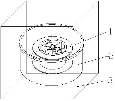
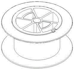
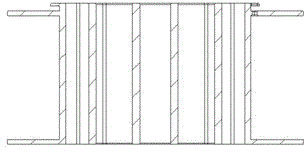
[0018] Such as figure 1 As shown, a temperature control system for controlling optical fiber temperature drift includes an optical fiber winding device 1 , an aluminum alloy cylinder 2 , and a glass fiber reinforced plastic cube box 3 . The optical fiber winder 1 with the optical fiber is placed inside the aluminum alloy cylinder 2, and the interior of the aluminum alloy cylinder 2 is filled with deionized water, and the deionized water submerges the optical fiber winder 1, and the body of the aluminum alloy cylinder 2 Add a sealing ring to seal between 6 and the cylinder cover 5 . The aluminum alloy cylinder 2 is suspended in the FRP cube box 3, and the gap between the aluminum alloy cylinder 2 and the FRP cube box 3 is filled with heat-insulating airgel 4. The outer wall of the whole fiberglass cube box 3 is wrapped with multi-layer heat insulating material.

[00...


PUM


Abstract

The invention discloses a temperature control system for controlling optical fiber temperature excursion and a control method of the temperature control system. An aluminum alloy cylinder is placed in the middle of a glass fiber reinforced plastic cubic box, and a gap between the aluminum alloy cylinder and the glass fiber reinforced plastic cube is filled by aerogel. Deionized water is fully filled inside the aluminum alloy cylinder, an optical fiber winder is submerged by the deionized water, and a sealing ring is added between the aluminum alloy cylinder and a cylinder cover for sealing. The outer surface of the whole cylinder is plated with silver coatings. A plurality of layers of heat insulation materials covers the outer wall of the glass fiber reinforced plastic cubic box of the whole device. The low heat conducting performance of the multilayer, the aerogel and the glass fiber reinforced plastics is utilized, and the influence on the inside optical fiber caused by external heat sources is prevented. Through the deionized water with great specific heat capacity and aluminum alloy liquid with good heat conducting performance adopted at the inside, the heating quantity generated by the optical fiber per se is diffused as soon as possible, and in addition, the caused temperature is diffused as little as possible. The temperature control system has the advantages that the temperature excursion of the optical fiber is effectively controlled, and distance measuring signals transmitted to the tail end of the optical fiber are enabled not to generate the distortion phenomenon.

Description

technical field [0001] The invention relates to a temperature drift control system and its application method, which is especially suitable for controlling the temperature drift of optical fibers. Background technique [0002] Pseudo-code ranging and carrier ranging have become important means of high-precision inter-satellite ranging. In order to realize the long-distance verification of the ranging accuracy of the pseudo-code ranging system and the two-way forwarding carrier ranging system, an optical fiber verification system was designed for the experiment. Based on the principle of optical fiber communication, the system realizes the long-distance transmission of ranging signals in optical fiber by utilizing the advantages of small size, small attenuation coefficient and strong anti-interference of optical fiber. Due to the nonlinearity and dispersion of light in the optical fiber transmission system, it is difficult to ensure that the ranging signal is completely free...

Claims


Application Information

Patent Timeline
Patent Type & Authority Patents(China)
IPC IPC(8): G05D23/01
Inventor 吴昌聚徐秀琴
Owner ZHEJIANG UNIV
Why Eureka
Try Eureka