Method and system for plane wave ultrasound imaging and microbubble imaging with compressive adaptive beamforming

An ultrasonic imaging method and adaptive beam technology, applied in ultrasonic therapy, radio wave measurement system, sound wave re-radiation, etc. Research on the transient characteristics of bubbles, etc.

Active Publication Date: 2016-04-27
XI AN JIAOTONG UNIV
View PDF6 Cites 0 Cited by
  • Summary
  • Abstract
  • Description
  • Claims
  • Application Information

AI Technical Summary

Problems solved by technology

However, for the transient physical information of microbubbles, the Line-by-line method of B-mode causes a time difference between different scanning lines of the same frame image, and its frame rate is generally 100Hz, so the time resolution cannot meet the needs of microbubbles. Study on the transient characteristics of
The Fink group proposed an ultra-fast active cavitation imaging method, which uses a full aperture to emit a plane wave along the axial direction to monitor the cavitation process, that is, the ultrasonic plane wave is used for microbubble imaging, but because the plane wave is emitted instead of focused ultrasound beam, which has poor sensitivity and lateral resolution
The team also used the plane wave composite fast ultrasonic imaging method for the detection and imaging of cavitation nucleation. This method realizes high frame rate real-time imaging through plane wave emission, and proposes that the coherent wave composite at different angles improves the imaging signal-to-noise ratio, but the improvement of the signal-to-noise ratio To a certain extent, the imaging frame rate is sacrificed, resulting in a decrease in the temporal resolution of the imaging, making it difficult to capture the instantaneous information of the microbubble dynamics

Method used


Image

  • Method and system for plane wave ultrasound imaging and microbubble imaging with compressive adaptive beamforming
  • Method and system for plane wave ultrasound imaging and microbubble imaging with compressive adaptive beamforming
  • Method and system for plane wave ultrasound imaging and microbubble imaging with compressive adaptive beamforming

Examples


Embodiment Construction

[0068] The present invention will be described in detail below in conjunction with the accompanying drawings and embodiments.

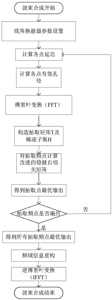
[0069] The present invention proposes a compression adaptive beamforming algorithm, as well as a method and system for plane wave ultrasonic imaging and microbubble imaging based on this, to overcome the existing technology in high frame rate, ultra-fast imaging, especially transient information Problems and limitations in imaging studies of characterized microvesicles. In the following, plane wave ultrasonic microbubble imaging is taken as an example for illustration.

[0070] A plane wave ultrasonic microbubble imaging system with compression adaptive beamforming, including an open programmable ultrasonic imaging system, an arbitrary waveform generator, a single-array focused ultrasonic transducer or a high-intensity focused ultrasonic transducer (HIFU) and a computer , the open programmable ultrasonic imaging system includes an ultrasonic linear a...


PUM


Abstract

The invention provides methods and systems for ultrasonic imaging and microbubble imaging of plane waves based on compressive adaptive beam forming. The compressive adaptive beam forming algorithm is adopted, each array element receives useful frequency point information of data, and the useful frequency point information is all centralized in effective bandwidth of an ultrasonic echo signal, so that the data in the effective bandwidth is subjected to compressive sensing treatment instead of the whole frequency domain, and on the basis of frequency-domain adaptive beam forming, the number of frequency-domain sampling points is reduced and calculated amount required during beam forming is reduced; plane wave imaging is adopted, so that a problem of transient change of microbubbles in conventional ultrasonic imaging is solved; the whole microbubble distribution region is covered by emitting planar ultrasonic waves once, so that a microbubble distribution image in the whole imaging plane is obtained; microbubble imaging of ultrasonic plane wave emission is adopted, so that the time resolution on microbubble imaging is very high.

Description

technical field [0001] The invention belongs to the technical field of ultrasonic detection and ultrasonic imaging, and specifically relates to a compression adaptive ultrasonic beam synthesis algorithm, and combined with plane wave ultrasonic emission, proposes a space-time high-resolution, high signal-to-noise ratio compression adaptive beam synthesis plane wave ultrasonic An imaging method and system, as well as a plane wave ultrasonic microbubble imaging method and system with high frame rate and low calculation amount of compressive adaptive beamforming. Background technique [0002] Delay and Sum (DAS) beamforming is a traditional, simple and most widely used imaging method in ultrasound imaging. It applies a specific delay to the ultrasound echo signals received by different channels and then sums them up to obtain the target focus signal. The DAS method is independent of the received echo signal and uses a predefined and fixed weighting coefficient, which does not m...

Claims


Application Information

Patent Timeline
Patent Type & Authority Patents(China)
IPC IPC(8): G01S15/89G01S7/539A61N7/00
Inventor 万明习柏晨徐姗姗敬博文
Owner XI AN JIAOTONG UNIV
Why Eureka
Try Eureka