Liquid drainage device used for electrochemical machining of interelectrode porous medium filling type mask

A porous medium and filling technology, which is applied in the direction of electrochemical processing equipment, processing working medium supply, metal processing equipment, etc., can solve the problem of large flow resistance of electrolyte, uneven distribution of flow field between electrodes, and affect the effect of electrolytic processing and speed to achieve the effect of small resistance and short discharge route

Inactive Publication Date: 2015-07-22
HENAN POLYTECHNIC UNIV
View PDF6 Cites 13 Cited by
  • Summary
  • Abstract
  • Description
  • Claims
  • Application Information

AI Technical Summary

Problems solved by technology

However, due to the relatively small pores in the flexible porous medium, the flow resistance of the electrolyte is large. When it is used to process a large-area workpiece, the electrolytic product may need to go through a long discharge ...

Method used


Image

  • Liquid drainage device used for electrochemical machining of interelectrode porous medium filling type mask
  • Liquid drainage device used for electrochemical machining of interelectrode porous medium filling type mask
  • Liquid drainage device used for electrochemical machining of interelectrode porous medium filling type mask

Examples


Embodiment Construction

[0023] Attached below Figures 1 to 5 The implementation of the present invention is further described.

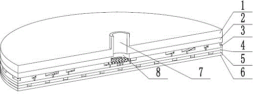
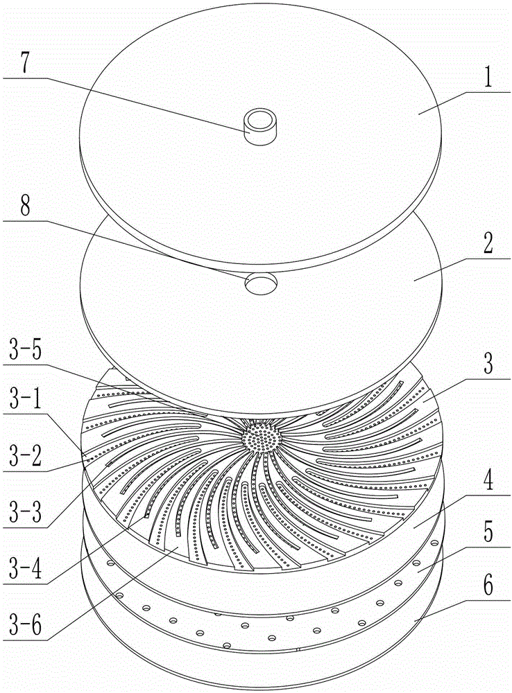
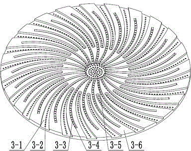
[0024] Such as Figures 1 to 5 As shown, a liquid introduction device for inter-electrode porous medium filled mask electrolytic processing, including a flat top cover 1 with a liquid inlet 7, a sheet-shaped gasket 2 with a central through hole 8 , a cathode 3 with through holes, a non-metallic flexible porous medium 4, a mask 5 and a workpiece anode 6; the front side of the cathode 3 is flat; the back side of the cathode 3 contains evenly distributed grooves and formed between two adjacent grooves The boss 3-6; the groove includes a circular sink 3-5 located in the center of the cathode 3, an arc-shaped drainage groove 3-3 evenly distributed in a windmill shape located in other areas except the sink 3-5, and The liquid outlet tank 3-1 installed between two adjacent drainage tanks; the drainage tank 3-3 is not connected to the liquid outlet tank 3-1; one end of the drain...


PUM

PropertyMeasurementUnit
Thicknessaaaaaaaaaa
Diameteraaaaaaaaaa
Diameteraaaaaaaaaa

Abstract

The invention discloses a liquid drainage device used for electrochemical machining of an interelectrode porous medium filling type mask. The liquid drainage device comprises a top cover, a sealing pad, a cathode, a non-metal flexible porous medium, the mask and a workpiece anode, wherein the front face of the cathode is flat, evenly distributed grooves and bosses formed between every two adjacent grooves are formed on the back face of the cathode; the grooves include a round liquid gathering groove located in the center of the cathode, arc drainage grooves located in the other areas except the liquid gathering groove and distributed in a windmill shape, and liquid outlet grooves formed between every two adjacent drainage grooves; the drainage grooves are not communicated with the liquid outlet grooves; liquid inlet holes are formed inside the liquid gathering groove and the drainage grooves; liquid outlet holes are formed inside the liquid outlet grooves; the top cover, the sealing pad, the cathode, the porous medium and the mask are tightly attached to the workpiece anode in sequence from top to bottom, and therefore a core machining unit is formed. The liquid drainage device enables electrolysate to be discharged more easily by directly changing the shape of the cathode, and enables a flow field on the surface of the workpiece anode to be distributed more evenly, thereby improving electrochemical machining quality.

Description

technical field [0001] The invention belongs to the field of electrolytic processing, and in particular relates to a liquid introduction device for electrolytic processing of a mask filled with a porous medium between electrodes. Background technique [0002] Reasonable micropit arrays, microgroove arrays and other surface textures can effectively reduce friction and wear, improve device surface heat dissipation and fluid movement, and are widely used. At present, the main methods of processing micropit arrays include laser processing, precision machining, electric discharge machining and electrolytic machining. Among them, electrolytic machining has the advantages of no direct contact between the tool and the workpiece, no tool electrode loss, high processing efficiency, and no processing stress, deformation, and heat-affected zone on the surface of the workpiece. important means. In general electrolytic machining, after a layer of photoresist is coated on the surface of ...

Claims


Application Information

Patent Timeline
IPC IPC(8): B23H3/00B23H3/10
CPCB23H3/00B23H3/10
Inventor 明平美张晓东秦歌周维海赵晨昊杨文娟
Owner HENAN POLYTECHNIC UNIV
Why Eureka
Try Eureka