
Quick road surface roughness detection system based on vehicle-mounted accelerometer

A detection system and accelerometer technology, which is applied in roads, roads, road repairs, etc., can solve the problems of high measurement environment requirements, high price, and complicated operation of detection methods, and achieve the effect of improving GPS accuracy

Active Publication Date: 2015-07-22
上海祎个科技有限公司
View PDF8 Cites 29 Cited by
  • Summary
  • Abstract
  • Description
  • Claims
  • Application Information

AI Technical Summary

Problems solved by technology

[0005] The object of the present invention is to provide a kind of road surface roughness rapid detection system based on vehicle-mounted accelerometer, the present invention uses triaxial acceleration sensor 1, angular velocity sensor 2, Zigbee short-range wireless communication module 3, touchable vehicle-mounted terminal 4, GPS5, The 3G remote module 6 and the central computer information processing module 7 are used to solve the problems of traditional detection methods such as complex operation, high price, and high requirements for the measurement environment, and at the same time realize the data connection with the traffic information center, making the road surface smoothness detection digital and intelligent , suitable for large-scale real-time road roughness measurement

Method used


Image

  • Quick road surface roughness detection system based on vehicle-mounted accelerometer
  • Quick road surface roughness detection system based on vehicle-mounted accelerometer
  • Quick road surface roughness detection system based on vehicle-mounted accelerometer

Examples


Embodiment Construction

[0034] The present invention will be described in detail below in conjunction with the accompanying drawings and specific embodiments.

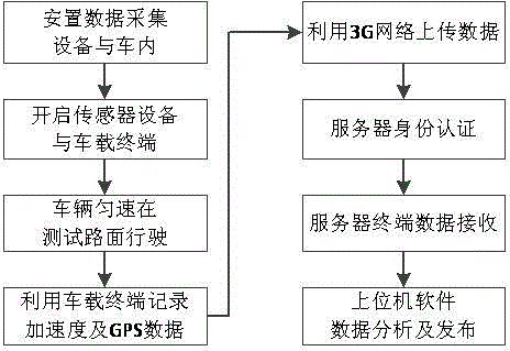
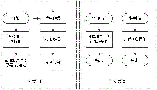
[0035] The invention relates to a rapid detection system for road surface roughness based on a vehicle-mounted accelerometer. The specific design is as follows: figure 1 As shown, the usage process is as follows figure 2shown. Including three-axis acceleration sensor 1, angular velocity sensor 2, Zigbee short-range wireless communication module 3, touchable vehicle terminal 4, GPS5, 3G remote module 6 and central computer information processing system 7. The Zigbee short-range wireless communication module and the three-axis acceleration sensor are placed on the single-chip microcomputer respectively, and combined with the small antenna 8, a data acquisition device 10 is made; the data acquisition device is arranged in the vehicle directly above the left and right rear axle wheels of the test vehicle, and is used to collect the driving proc...


PUM


Abstract

The invention relates to a quick road surface roughness detection system based on a vehicle-mounted accelerometer. The system comprises a three-axis acceleration sensor, an angular velocity sensor, a Zigbee short-range wireless communication module, a touchable vehicle-mounted terminal, a GPS (global positioning system) and a central computer information processing system, wherein the Zigbee short-range wireless communication module and the three-axis acceleration sensor are integrated to form data acquisition equipment, and the data acquisition equipment is used for acquiring acceleration values produced during riding of a vehicle and performs internal short-range wireless transmission; the GPS, the angular velocity sensor and a 3G remote module are used for recording geographic coordinates of the riding vehicle and turn angle conditions of the riding vehicle and transmit packed files to a server; the touchable vehicle-mounted terminal is used for acquiring acceleration sensor data and matching the acceleration sensor data with GPS data and angular velocity data by using a time sequence to generate initial data; the central computer information processing system is used for directionally receiving data sent by the to-be-detected vehicle and processing the data to acquire an estimated IRI (internal roughness index) / RQI (riding quality index) to be displayed on an electronic map. The system is used for solving problems that traditional detection methods are time-consuming, labor-consuming, low in efficiency, high in price and the like and monitors the road surface roughness in real time.

Description

technical field [0001] The invention belongs to the technical field of road surface quality detection and automatic information collection, and in particular relates to a rapid detection system for road surface smoothness based on a vehicle-mounted accelerometer. Background technique [0002] Road surface roughness is an important index to measure road service level, and it is also one of the main causes of traffic accidents. The traditional flatness detection methods such as laser flatness meter, profiler, 3-meter ruler, and level have disadvantages such as complicated operation, high price, and high requirements for the measurement environment, and are not suitable for large-scale flatness detection. [0003] The road surface roughness measurement methods and equipment can be roughly divided into three categories, namely, the reaction type flatness meter, the section type roughness meter and the subjective evaluation method. The cross-section roughness meter measures the ...

Claims


Application Information

Patent Timeline
Patent Type & Authority Applications(China)
IPC IPC(8): E01C23/01
CPCE01C23/01
Inventor 刘成龙杜豫川吴荻非孙立军李思雨
Owner 上海祎个科技有限公司
Learn More