Airflow thermal insulation rubber hose assembly for high-temperature thermal radiation environment

A rubber hose, heat radiation technology, applied in the direction of protecting pipes, pipe elements, pipes/pipe joints/pipe fittings through thermal insulation, etc. Problems such as heat transfer from the heat-disconnecting source and performance degradation at the connection of the hose assembly can reduce the consumption of spare parts, make production faster, and reduce the investment of manpower and financial resources.

Active Publication Date: 2015-07-22
SHANGHAI OUJI FLUID POWER CO LTD
View PDF11 Cites 1 Cited by
  • Summary
  • Abstract
  • Description
  • Claims
  • Application Information

AI Technical Summary

Problems solved by technology

[0006] 2. Failure to effectively protect the hose joint 4 and sleeve 3
The length of the protective layer 2 generally does not exceed the distance between the outer end faces of the two sleeves 3, the joint 4 and the sleeve 3 are basically exposed, and the specific heat capacity of the joint 4 and the sleeve 3 of the hose is 1/4 of that of the rubber hose, and the joint 4 Absorb heat and heat up quickly, the temperature is high, and the heat will be transferred to the hose rubber layer at the joint, which will accelerate the aging of the hose body 1 and affect the quality of the joint
Therefore, the long-term effect of excessive temperature accelerates the aging of the rubber of the hose body 1, and continuously reduces the performance of the jo

Method used


Image

  • Airflow thermal insulation rubber hose assembly for high-temperature thermal radiation environment
  • Airflow thermal insulation rubber hose assembly for high-temperature thermal radiation environment
  • Airflow thermal insulation rubber hose assembly for high-temperature thermal radiation environment

Examples


Embodiment 1

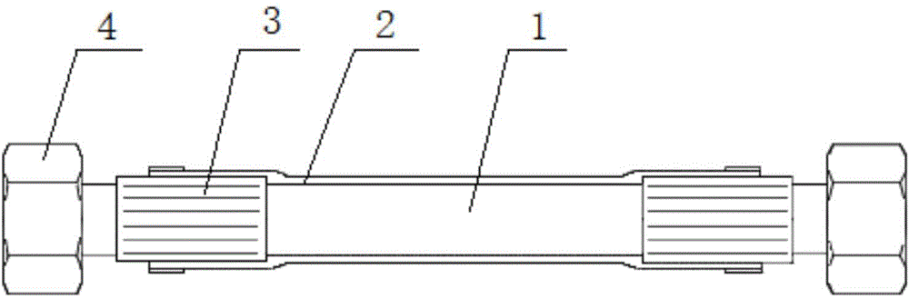
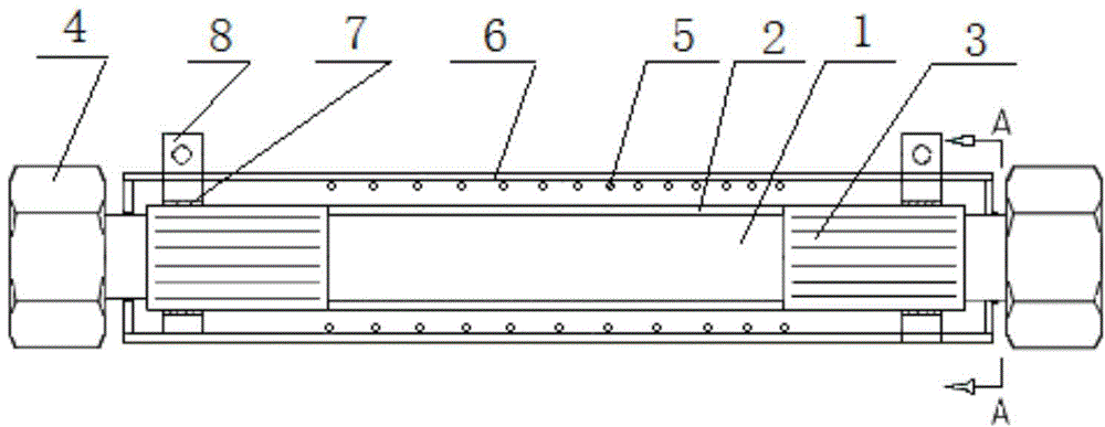
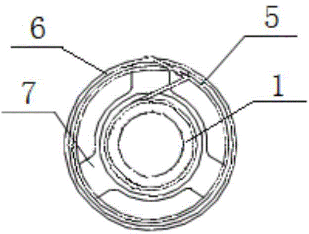
[0033] Embodiment 1: as attached figure 1 As shown, the two ends of the hose body 1 are respectively connected to the joints 4, the two joints (4) and the hose body (1) are connected through the sleeve (3), the protective layer 2 is covered between the two sleeves 3, and the protective layer 2 The elastic support frame 5 of the jacket wraps the outer sheath 6 outside the elastic support frame 5 .

[0034] In the foregoing, the positioning sliding rings 7 are fitted outside the sleeve 3 respectively, and the outer edge of the positioning sliding ring 7 abuts against the inner wall of the outer sheath 6 .

[0035] In the foregoing, the elastic support frame 5 is a spring, which is made of existing general-purpose materials and techniques, with sufficiently long straight ends left at both ends, and corresponding heat treatment is carried out to facilitate winding on the neck of the hose joint; the elastic support frame 5 supports Outer sheath 6, and guarantee that flexible pipe ...

Embodiment 2

[0039] Embodiment 2: as attached Figure 6As shown in , when the radiant heat is very strong, in order to reduce the heat absorbed by the joint 4 and conduct it to the rubber hose body 1, the inner diameter of the outer sheath 6 and the elastic support frame 5 is increased, and the length of the outer sheath 6 is lengthened. Even exceeding the total length of the hose assembly, and making it extend the wrap around the joints 4 at both ends, the heat conduction distance can be extended. The length of the outer sheath 6 is greater than the distance between the outer faces of the joints 4 at both ends, and the inner diameter of the outer sheath 6 and the elastic support frame 5 is greater than the maximum outer diameter of the joint 4 and the joint connected thereto. When assembling and disassembling the hose assembly, the elastic support frame 5 can be axially compressed, and the joints 4 at both ends can be exposed.

Embodiment 3

[0040] Embodiment 3: as attached Figure 7 As shown; that is, as in Embodiment 2, the neck of the joint 4 and the length of the outer sheath 6 can also be lengthened at the same time.

[0041] The above three examples can choose the best solution according to the specific situation of radiant heat and installation conditions.

[0042] In the present invention, the hose body 1 is flexible, and both the direction of the pipeline and the movement of the equipment require the bending of the hose assembly. The elastic support frame 5 of the spring structure has small bending force and small radial deformation. The movable structure at both ends can Compensate for the inconsistent length change of the outer sheath 6 and the hose body 1 during bending; the neck winding structure of the joint 4 at both ends of the elastic support frame 5 can stretch the elastic support frame 5 when the length compensation is not enough to ensure that it is wrapped in the outer sheath 6 The inner slee...


PUM


Abstract

Provided is an airflow thermal insulation rubber hose assembly for a high-temperature thermal radiation environment. The two ends of a hose body (1) are each connected with a connector (4), the two connectors (4) are connected with the hose body (1) through sleeves (3), the part between the two sleeves (3) is sleeved with a protecting layer (2), the protecting layer (2) is sleeved with an elastic supporting frame (5), and an outer sheath (6) is wrapped on the elastic supporting frame (5). An annular gap is formed between the hose assembly and a combination of the elastic supporting frame (5) and the outer sheath (6), so that the heat transfer problem is solved, protection of the hose connectors is enhanced, the quantity of heat absorbed by the hose body and the hose connectors is reduced, the temperature of the hose body and the hose connectors is decreased, the service life of the hose assembly is prolonged, and the rubber hose body can be used for a long time in the high-temperature heat source environment. Effective fire retarding and thermal radiation resistance protection can be conducted on the ends of the hose body and the connectors, and fire retarding and thermal radiation resistance performance is greatly improved. The service life is three times longer than that in existing protection methods, and the probability that the hose body suffers from random failures is reduced.

Description

technical field [0001] The invention relates to the support of IPC classification F16L pipes, cables or protective pipes and the heat insulation method and equipment, especially the airflow heat insulation rubber hose assembly in the high temperature heat radiation environment. Background technique [0002] Hoses are vital components in modern industry. Hoses are mainly used as wire and cable protection tubes for wires, cables, automated instrument signals, and civil shower hoses, with specifications ranging from 3mm to 150mm. Small-diameter hose (3mm-25mm inner diameter) is mainly used for the protection of sensing lines of precision optical rulers and industrial sensor lines. Threading hoses are mainly hoses made of galvanized steel strips, stainless steel strips, PA, PE, PP and other plastic materials. The advantages are good elasticity, low stiffness, good toughness, twist resistance, good bending performance, and can withstand heavy loads; acid, lubricating oil, coola...

Claims


Application Information

Patent Timeline
IPC IPC(8): F16L53/00F16L55/07
CPCF16L53/00F16L55/07F16L59/02
Inventor 朱亮华
Owner SHANGHAI OUJI FLUID POWER CO LTD
Why Eureka
Try Eureka