
High-temperature push-pull fatigue test clamp for hollow round rod test piece

A hollow round bar, fatigue test technology, applied in the direction of measuring devices, instruments, scientific instruments, etc., can solve the problems of forming temperature gradient, construction, unable to hold hollow round bar specimens, etc., to reduce heat transfer and reduce fixture temperature. , the effect of convenient processing

Active Publication Date: 2015-07-22
廊坊智驰动力科技有限公司
View PDF9 Cites 27 Cited by
  • Summary
  • Abstract
  • Description
  • Claims
  • Application Information

AI Technical Summary

Problems solved by technology

However, there are two significant problems in the design of the tension / compression fatigue fixture of the hollow round bar specimen: (1) how to eliminate the screw connection gap between the specimen and the fixture to carry out the tension / compression fatigue test; (2) how to Design the cooling air flow channel to cool the inside of the test piece and form a temperature gradient
This patent is designed for solid round rod specimens, the fixture cannot provide cooling airflow inside the specimen, forming a temperature gradient
[0010] In summary, the existing technology cannot be used for the clamping of standard hollow rod specimens, nor can it complete the construction of the temperature gradient in the wall thickness direction of the specimen; at the same time, it cannot provide compressive load, and cannot provide cooling airflow inside the specimen

Method used


Image

  • High-temperature push-pull fatigue test clamp for hollow round rod test piece
  • High-temperature push-pull fatigue test clamp for hollow round rod test piece
  • High-temperature push-pull fatigue test clamp for hollow round rod test piece

Examples


Embodiment Construction

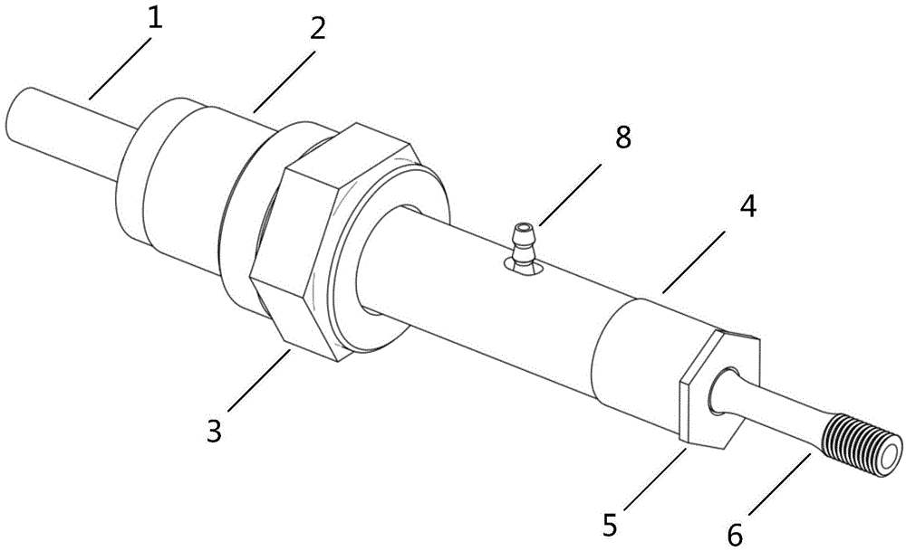
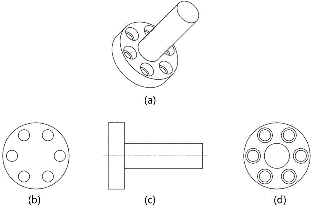
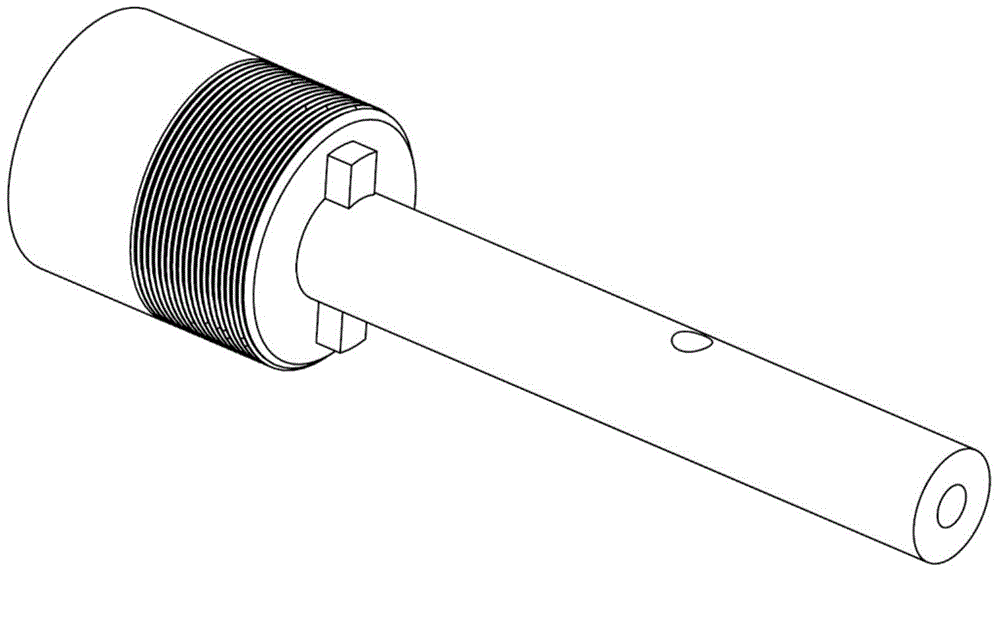
[0030] The invention is mainly designed for a high-temperature fatigue fixture with a cooling channel suitable for a hollow round bar test piece. In fact, during the test, the whole set of fixtures includes two fixtures of the present invention, which are divided into upper fixtures and lower fixtures. The general diagram of complete installation is shown in Figure 9 . First assemble the upper and lower fixtures separately:

[0031] Such as figure 1 , 2 , As shown in 3, 4, 5, 6, 7, and 10, first assemble the fixture. Connect and tighten the joint 1 and the thick end of the connecting rod 2 through six countersunk bolts 7, and then insert the sleeve 4 into one end of the hollow rod of the connecting rod 2. The two small teeth fit together, so that unnecessary rotation can be prevented, and at the same time, the relative positions of the connecting rod 2 and the sleeve 4 can be accurately positioned to facilitate subsequent installation of the cooler joint 8. At this time,...


PUM


Abstract

The invention discloses a high-temperature push-pull fatigue test clamp for a hollow round rod test piece, wherein the hollow round rod test piece is cooled by an air flow inside during a high-temperature test, so that a required temperature gradient on the inner and outer wall surfaces of the hollow round rod test piece during the high-temperature test is realized; a hydraulic chuck of a fatigue machine clamps a light rod end of a joint and is connected with a connecting rod through a countersunk bolt; the connecting rod and a sleeve are fastened by virtue of a nut; the test piece is fastened into a test piece cover and the two are fastened into the sleeve together and are ejected by the hollow rod end of the connecting rod to eliminate the thread pitch; the cooling air flow from a compressor passes through the joint of a cooler, passes through the sleeve through a relatively large hole and enters into the inner cavity of the connecting rod so as to further enter into the hollow round rod test piece to enter into the test piece downward and to be discharged through a lower clamp. The clamp disclosed by the invention can be used for stably clamping the hollow round rod test pieces of various dimensions and uniaxial elongation and elongation / compression fatigue of the test piece under a high temperature condition is realized.

Description

technical field [0001] The invention relates to metal material fatigue performance test equipment, in particular to the field of design and manufacture of metal material uniaxial high-temperature tension / compression fatigue test fixtures. Background technique [0002] Aeroengine turbine blades have harsh service conditions (high temperature, high pressure, high speed, gas corrosion, etc.), and the blade materials are subjected to alternating mechanical and thermal loads. It is of great significance to carry out fatigue tests of blade materials under complex and extreme working conditions to study their fatigue performance. At present, most high-pressure turbine blades are hollow air-cooled blades, and there is a high temperature difference between the inner and outer walls of the blades, resulting in a significant temperature gradient in the direction of the wall thickness of the blades. Studies have shown that the existence of temperature gradients changes the damage mecha...

Claims


Application Information

Patent Timeline
Patent Type & Authority Applications(China)
IPC IPC(8): G01N3/04
Inventor 王荣桥蒋康河胡殿印申秀丽樊江
Owner 廊坊智驰动力科技有限公司
Learn More