
Turbidity meter

A turbidimeter and sample cell technology, used in instruments, scientific instruments, scattering characteristics measurement, etc., can solve problems such as inability to measure high-temperature fluid turbidity, and achieve the effect of structural improvement, avoiding high-temperature damage, and material optimization.

Active Publication Date: 2015-07-22
SHANGHAI INST OF APPLIED PHYSICS - CHINESE ACAD OF SCI
View PDF5 Cites 5 Cited by
  • Summary
  • Abstract
  • Description
  • Claims
  • Application Information

AI Technical Summary

Problems solved by technology

[0003] The purpose of the present invention is to provide a turbidity meter, thereby solving the defect that the turbidity meter in the prior art cannot measure the turbidity of high-temperature fluid

Method used


Image

  • Turbidity meter
  • Turbidity meter

Examples


Embodiment Construction

[0032] The present invention will be further described below in conjunction with specific embodiments. It should be understood that the following examples are only used to illustrate the present invention but not to limit the scope of the present invention.

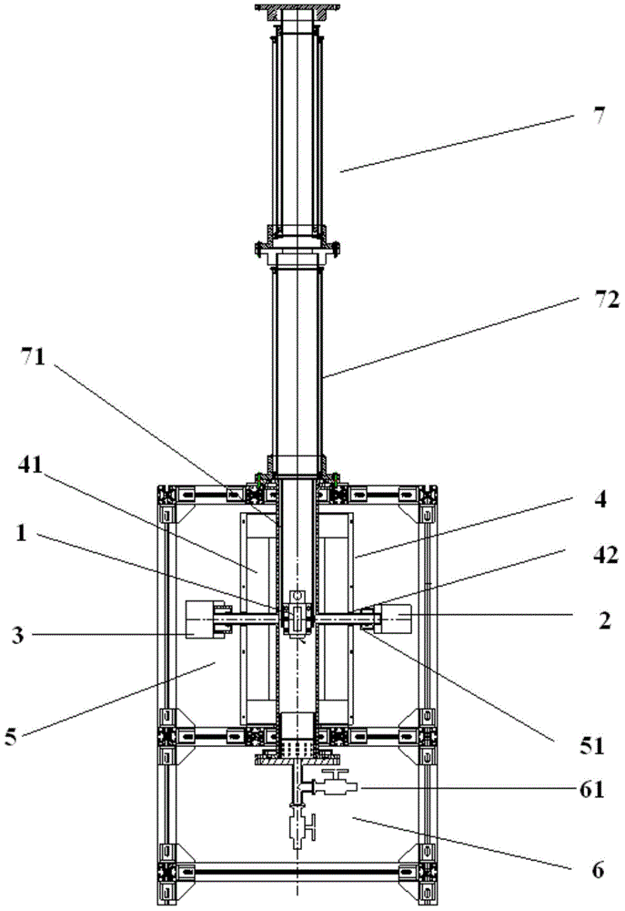
[0033] Such as figure 1Shown is a turbidimeter according to a preferred embodiment of the present invention, which mainly includes: a sample cell 1, a light source 2, a detector 3, a heating system 4, a cooling system 5, a vacuum system 6, and a lifting system 7, and a control system for controlling the light source 2 and the detector 3, the control system includes a converter (not shown) for converting the signal collected by the detector.

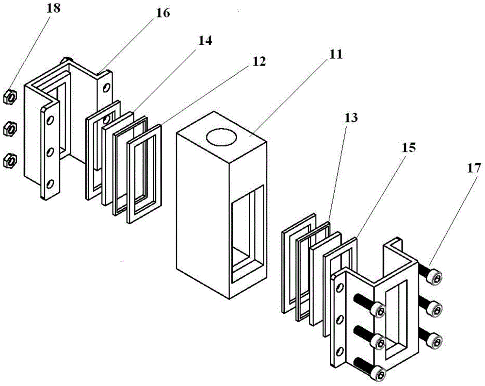
[0034] In this embodiment, the structure of the sample cell 1 is as figure 2 As shown, it mainly includes: a sample cell main body 11, a first sealing ring 12, a protection ring 13, a window 14, a second sealing ring 15, and a gland 16, wherein the first sealing ring 12, the windo...


PUM


Abstract

The invention provides a turbidity meter. The turbidity meter comprises a sample tank, a light source and a detector and a control system, and further comprises a heating system and a cooling system, wherein the light source and the detector are fixed on the two sides of the sample tank respectively; the control system is used for controlling the light source and the detector; the heating system is used for heating a sample to be heated; the heating system comprises a heating furnace for providing a sealed space and storing the sample tank; the heating furnace is further provided with an optical window for allowing light to pass through; the sample tank comprises a sample tank main body made of a high-temperature-resisting and corrosion-resisting material, and a window plate which is made of a high-temperature-resisting and corrosion-resisting material and through which visible light and near-infrared light pass; and the window plate is aligned to the optical window. The turbidity meter provided by the invention is additionally provided with the heating system and the cooling system, and the matched and designed sample tank, so that the turbidity of a sample with the temperature more than 200 DEG C and having corrosion is metered; and the turbidity meter has the advantages of good safety, strong operability, wide applicable range and the like.

Description

technical field [0001] The invention relates to the technical field of an instrument device for turbidity detection, in particular to a turbidity meter. Background technique [0002] Molten salt has been widely used in the fields of solar energy and nuclear energy due to its excellent thermophysical properties and heat transfer and storage properties. Lithium fluorine beryllium molten salt is used as the main coolant of the fourth-generation reactor-molten salt reactor, and its "cleanliness" means the concentration of insoluble impurities, which has an important impact on the operation of the reactor. Using HF-H 2 In the process of chemically purifying fluorine lithium beryllium molten salt, the corrosion product Ni in the molten salt will be 2+ , Fe 3+ , Cr 3+ The metal ions are reduced to metal powder, resulting in an increase in the concentration of insoluble substances in the molten salt during the operation of the stack. The solid particles in the molten salt will ...

Claims


Application Information

Patent Timeline
Patent Type & Authority Applications(China)
IPC IPC(8): G01N21/59G01N21/47G01N21/01G01N21/03
Inventor 苏涛汤睿张鹏谢雷东侯惠奇
Owner SHANGHAI INST OF APPLIED PHYSICS - CHINESE ACAD OF SCI
Learn More