
Instant milling force prediction method in variable-curvature curved surface side milling process

A technology of instantaneous milling force and prediction method, which is applied in special data processing applications, instruments, electrical digital data processing, etc., and can solve problems such as inaccurate calculation results of feed per tooth, a large number of mathematical calculations, and inability to obtain NC codes, etc.

Active Publication Date: 2015-07-22
NANJING INST OF TECH
View PDF3 Cites 18 Cited by
  • Summary
  • Abstract
  • Description
  • Claims
  • Application Information

AI Technical Summary

Problems solved by technology

[0006] Literature 1 and Literature 2 take the distance between two adjacent teeth and the intersection of the surface to be processed as the actual feed per tooth, without considering the influence of the feed direction, resulting in inaccurate calculation results of the actual feed per tooth, thus The calculation of instantaneous undeformed chip thickness is inaccurate, and the prediction of milling force is not accurate enough
Document 3 is based on the method of NC code to determine the tool position path. Although it is closer to the actual machining, it cannot obtain the correct NC code when the milling parameters are not determined. Therefore, the method is not suitable for milling parameter optimization and other fields.
In addition, when calculating the cut-in / cut-out angle in Document 1, Document 2 and Document 3, a large number of mathematical calculations are required, which affects the efficiency of milling force prediction

Method used


Image

  • Instant milling force prediction method in variable-curvature curved surface side milling process
  • Instant milling force prediction method in variable-curvature curved surface side milling process
  • Instant milling force prediction method in variable-curvature curved surface side milling process

Examples


example

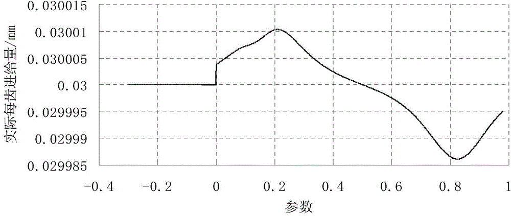
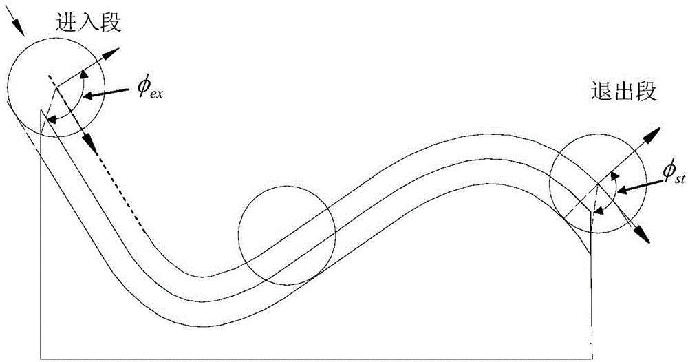
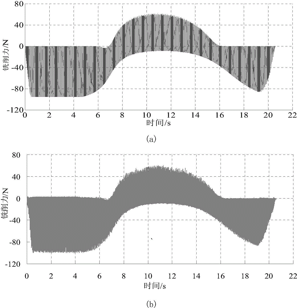
[0122] (1) Select tool radius R=5mm, helix angle β=35°, number of cutter teeth N f =4, the Al6061 material is processed on a three-coordinate vertical milling machine; the spindle speed n r =3000r / min, axial depth of cut a p = 2mm, nominal radial depth of cut a e =3mm, nominal feed per tooth f z =0.03mm / r, down milling; sampling point parameter interval Δu=0.00002; the parameter equation of workpiece contour curve after processing is:

[0123] x(u)=50u, y(u)=-80u-0.2≤u≤0;

[0124] x(u)=75u+15u 2 -10u 3 , y(u)=-120u+360u 2 -240u 3 0≤u≤1.

[0125] The left boundary of the blank is:

[0126] x=-10.

[0127] The right boundary of the blank is:

[0128] x=80.

[0129] (2) Calculate the corresponding tool path curve parameter u when the tool starts cutting material 0 =-0.2995, let u=u 0 , l=0, F x = 0, F y =0, calculate tool center position x t (u)=-10.7328, y t (u)=26.6064.

[0130] (3) order u pre =u,x t (u pre )=x t (u),y t (u pre )=y t (u), u=u+Δu, l...


PUM


Abstract

The invention discloses an instant milling force prediction method in the variable-curvature curved surface side milling process. The method includes the steps of calculating position points of all tools along tracks of the tools at equal parameter intervals according to the variable curvature characteristic of a curved surface in the side milling process, calculating instant tool angular positions, feed directions, corresponding machining times and actual radial cutting depths, calculating the instant cut-in / cut-out angles according to the actual radial cutting depths, using the nominal feed engagement of each tooth as the actual feed engagement of each tooth, calculating the instant non-deformation cutting thickness of each cutting micro-unit through the combination with the instant tool angular positions, establishing a milling force model under a local coordinate system according to the feed directions, projecting the milling force model into a whole coordinate system, and then obtaining the instant milling force. By means of the method, the milling force prediction efficiency is high in the variable-curvature curved surface side milling process, and the milling force prediction is accurate.

Description

technical field [0001] The invention relates to a method for predicting milling force during milling, and more particularly, to a method for predicting instantaneous milling force during side milling of complex curved surfaces. Background technique [0002] Milling force is one of the most important physical parameters in the milling process. It directly affects the deformation of the tool and workpiece, milling stability, tool wear, etc., thus affecting the machining accuracy, machining efficiency and energy consumption. At present, the research on the milling force in the process of side milling mainly focuses on linear milling (zero curvature) and circular arc milling (constant curvature). In these two cases, due to the invariance of cutting geometric conditions, the milling force changes periodically. In the fields of aviation, mold, automobile and electronics, the curvature of most complex surfaces is constantly changing. Due to the influence of curvature, the actual ra...

Claims


Application Information

Patent Timeline
IPC IPC(8): G06F17/50
Inventor 王保升郝洪艳汪木兰侯军明冯勇王善华
Owner NANJING INST OF TECH
Learn More