High-speed electric machine electromagnetism structure for air compressor
A technology of electromagnetic structure and high-speed motor, which is applied in the shape/pattern/structure of magnetic circuit, electromechanical device, shape/pattern/structure of winding conductor, etc. Achieve high speed, high power density and reduce harmonic loss
- Summary
- Abstract
- Description
- Claims
- Application Information
AI Technical Summary
Problems solved by technology
Method used
Image

Examples
Embodiment 1
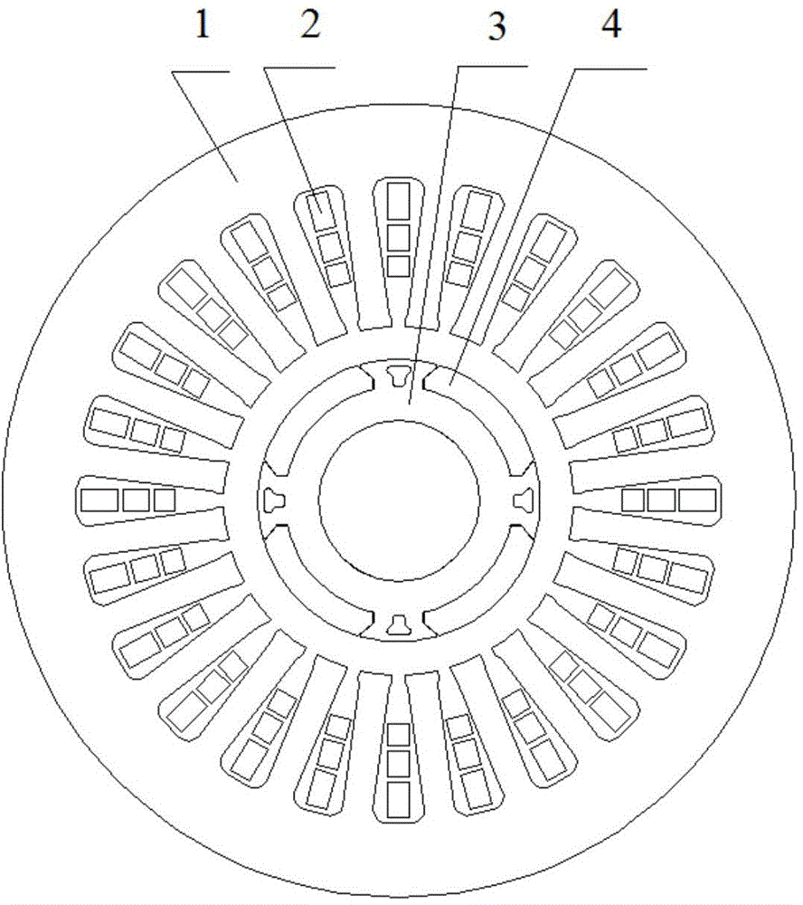
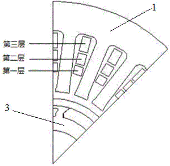
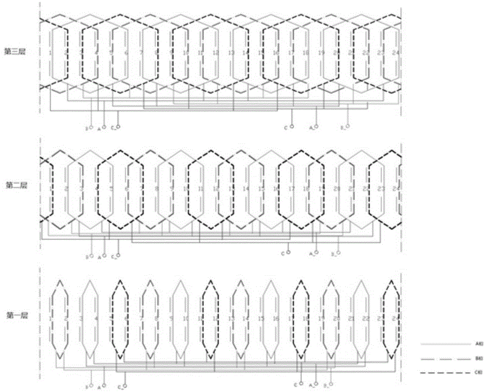
[0039] Such as Figure 1-5As shown, an electromagnetic structure of a high-speed motor for an air compressor, the electromagnetic structure includes a stator core 1, a stator winding 2 arranged on the stator core 1, a rotor core 3, and a permanent magnet embedded on the surface of the rotor core 3 The magnet 4, the stator core 1 is evenly arranged with multiple rows of stator slots along the circumference, the stator winding 2 is arranged in the stator slots in the connection mode of three layers of low harmonic concentric windings, and the surface of the rotor core 3 is evenly arranged with multiple rows along the circumference Two wedge-shaped grooves, wedge-shaped arms 5 are arranged between adjacent two wedge-shaped grooves, and air magnetic isolation holes 6 for increasing the amplitude of the air-gap flux density are arranged on the wedge-shaped arms 5, and the permanent magnet 4 is embedded in the wedge-shaped grooves to work When the rotor core 3 is running at a high s...
Embodiment 2
[0044] In this embodiment, there are 6 wedge-shaped grooves in total, which are arranged on the surface of the rotor core 3 in the axial direction, and the permanent magnet 4 is embedded in the wedge-shaped grooves in the axial direction, and the groove angle of the wedge-shaped grooves is 50°. The air magnetic isolation hole is a T-shaped air magnetic isolation hole, and the area of the air magnetic isolation hole is 1 / 2 of the area of the wedge arm. All the other are with embodiment 1.
Embodiment 3
[0046] In this embodiment, there are 8 wedge-shaped slots in total, which are arranged on the surface of the rotor core 3 in the axial direction, and the permanent magnet 4 is embedded in the wedge-shaped slots in the axial direction, and the slot angle of the wedge-shaped slots is 60°. The air magnetic isolation hole is a T-shaped air magnetic isolation hole, and the area of the air magnetic isolation hole is 1 / 3 of the area of the wedge arm. All the other are with embodiment 1.
PUM
 Abstract
Description
Claims
Application Information