
Spiral stepping motor stator and rotor mechanism and spiral stepping motor

A stepping motor and stator technology, applied in the field of motors, can solve the problems of high positioning accuracy, low production cost and low positioning accuracy of two moving parts, and achieve the effects of simplifying the structure, saving costs and reducing costs.

Active Publication Date: 2015-07-22
俞富春
View PDF4 Cites 6 Cited by
  • Summary
  • Abstract
  • Description
  • Claims
  • Application Information

AI Technical Summary

Problems solved by technology

[0003] Although there is a motor that can satisfy the two parts to perform different movements at the same time, and integrates the power and transmission mechanism, its positioning accuracy is low and the production cost is high.
[0004] Therefore, there is such a problem in the structure of the known motor: it is impossible to have two moving parts and at the same time, it must have high positioning accuracy, low production cost and integrate power and transmission mechanism.

Method used


Image

  • Spiral stepping motor stator and rotor mechanism and spiral stepping motor
  • Spiral stepping motor stator and rotor mechanism and spiral stepping motor
  • Spiral stepping motor stator and rotor mechanism and spiral stepping motor

Examples


Embodiment 1

[0066] Embodiment 1 can use open-loop control.

[0067] Figure 15 It is a block diagram of open-loop control. Closed-loop control includes a power supply 44, a controller 43, a driver 45, and a motor body 46. The controller 43 controls the direction, speed, torque, and thrust of the motor. The information output by the controller 43 is passed through The driver 45 drives the motor body 46, and the power supply 44 provides electric energy for the whole system.

[0068] b) Closed loop control.

Embodiment 2

[0069] Embodiment 2 can use closed-loop control.

[0070] Figure 16 It is a block diagram of closed-loop control, which includes a power supply 44, a controller 43, a driver 45, information feedback 48, and a motor body 46; wherein the controller 43 controls the motor's direction, speed, torque, and thrust. The information output by the controller 43 drives the motor body 46 through the driver 45, and the motor running status 48 feeds back the real-time running status information of the motor to the controller 43 for comparative control, and the power supply 44 provides electric energy for the whole system.


PUM


Abstract

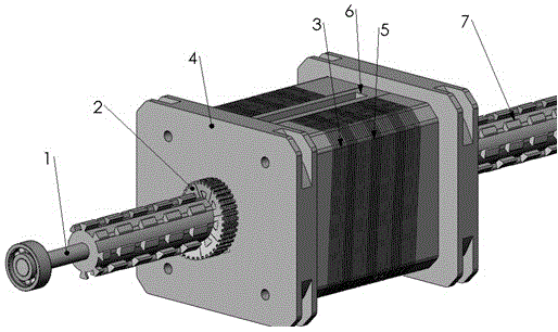
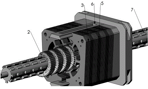
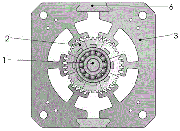
Disclosed is a spiral stepping motor stator and rotor mechanism. A rotor comprises a central shaft and a plurality of rotor blocks, the rotor blocks are evenly arranged on a central circumference, adopting the central shaft as the shaft center and adopting one cylindrical post spiral line as a reference line, continuously or at intervals. A stator comprises a plurality of stator blocks, partitions and a cover plate. The stator blocks and the rotor blocks remain same distance radially, the operation surface axial width of the stator blocks is consistent with that of rotor blocks, and the stator blocks are flushed with the rotor blocks. When the motor operates, a dynamic spiral magnetic field is generated between the stator blocks and the rotor blocks, under the effect of the spiral magnetic field, the rotor blocks and the stator blocks perform non-friction linear and circumferential movements. The spiral stepping motor allows two components to perform circumferential movement and linear movement respectively and simultaneously or one component to perform circumferential movement and linear movement simultaneously.

Description

technical field [0001] The invention relates to a motor, in particular to a helical stepping motor in which a stator and a rotor can simultaneously move in different modes. Background technique [0002] Most of the existing motors are single moving parts. When two parts in the system need to move in different modes at the same time or the same part needs both circular motion and linear motion, it must be converted through an intermediate mechanism, resulting in complex structure and bulky equipment. Huge and expensive. The rotary motor must go through the intermediate link to achieve its linear drive capability. Although the linear motor has advantages in linear drive, it is expensive. Moreover, they have one characteristic in common: only one moving part. [0003] Although there is an electric motor that can satisfy the two parts to perform different movements at the same time, and also integrates the power and the transmission mechanism, its positioning accuracy is low a...

Claims


Application Information

Patent Timeline
Patent Type & Authority Applications(China)
IPC IPC(8): H02K37/00
CPCH02K37/00
Inventor 俞富春
Owner 俞富春
Learn More