
Active current ripple suppression method for hybrid microgrid bidirectional converter with DC grid-connected operation

A bidirectional converter and current ripple technology, applied in the direction of output power conversion devices, electrical components, etc., can solve problems such as difficult installation and maintenance, endangering the safe operation of the system, and short operating life, so as to save investment and operating costs, and reduce ripple Significant inhibitory effect and reduced investment and operating costs

Active Publication Date: 2017-06-16
SHANDONG UNIV
View PDF5 Cites 0 Cited by
  • Summary
  • Abstract
  • Description
  • Claims
  • Application Information

AI Technical Summary

Problems solved by technology

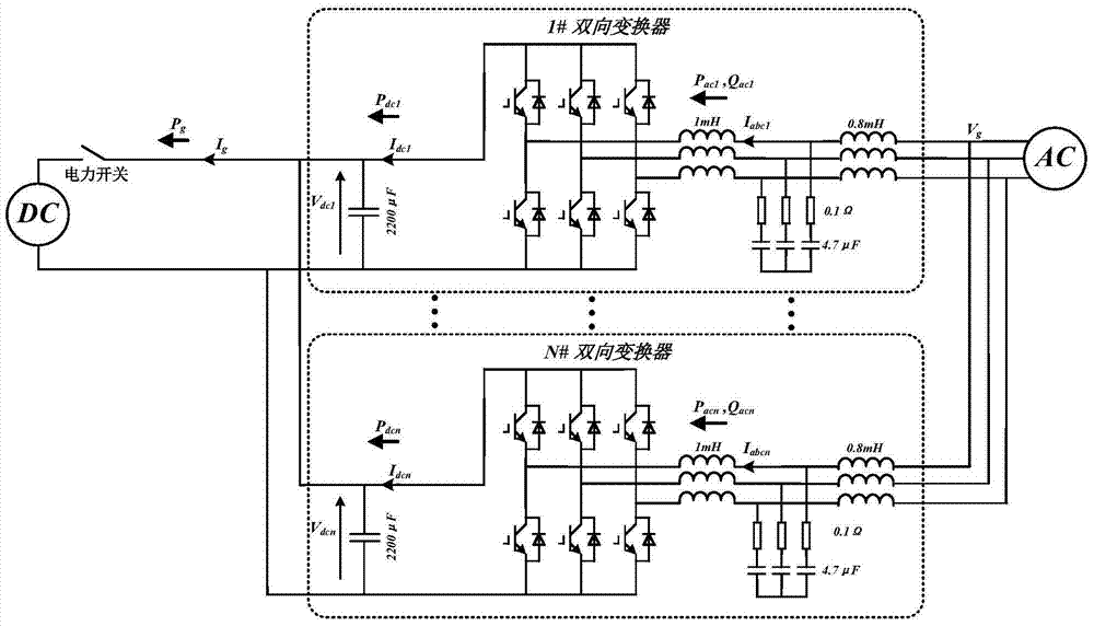
[0005] However, in order to meet the higher power requirements of the hybrid microgrid, multiple bidirectional converters between the AC and DC subnets will be connected in parallel, which will cause serious DC current ripple problems when the DC side is connected to the grid.
The root cause is that under the parallel structure, the equivalent output impedance of the AC side and DC side of the bidirectional converter and the filter impedance form an impedance network that is a function of frequency, forming resonance at different frequency points, resulting in serious current ripples and increasing circuit losses. , shorten the life of power electronic devices and filters, and also cause abnormal operation of sensitive equipment in the DC subnet in the hybrid microgrid, and even cause equipment failure, endangering the safe operation of the system
[0006] In order to suppress the ripple current, the traditional passive suppression method adopts increasing the capacitance value or increasing the inductance value, which is not only bulky, difficult to install and maintain, but also significantly increases system investment and operating costs
The traditional active suppression method can also use battery energy storage equipment to absorb ripple power, but battery energy storage not only has a slow response time, is relatively expensive, but also has a short operating life, complicated control and maintenance, and economical operation of hybrid microgrids. Contradictory goals

Method used


Image

  • Active current ripple suppression method for hybrid microgrid bidirectional converter with DC grid-connected operation
  • Active current ripple suppression method for hybrid microgrid bidirectional converter with DC grid-connected operation
  • Active current ripple suppression method for hybrid microgrid bidirectional converter with DC grid-connected operation

Examples


Embodiment Construction

[0042] The present invention will be further described below in conjunction with the accompanying drawings and embodiments.

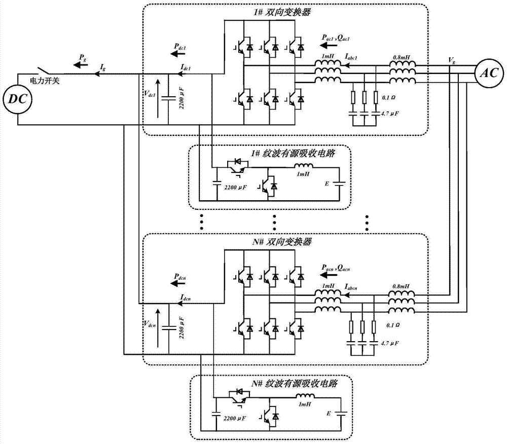
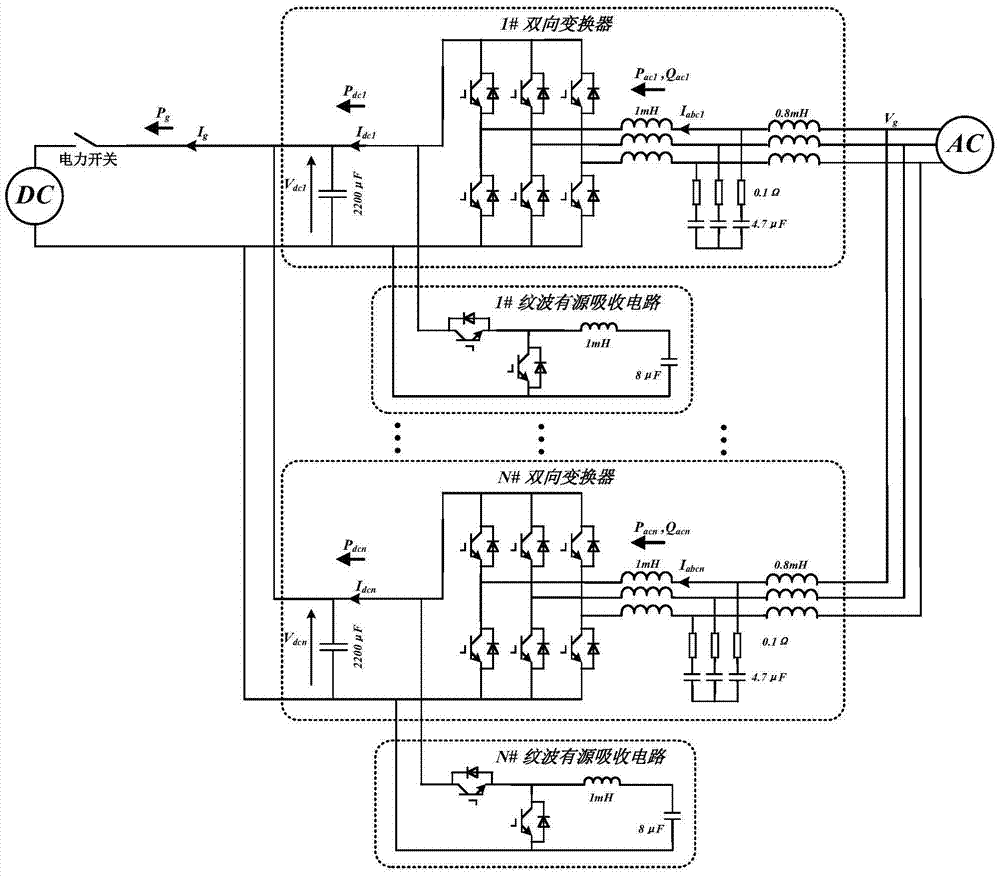
[0043] The ripple current active suppression circuit includes a single-phase bridge arm, the bridge arm includes two series-connected IGBT tubes, the bridge arm is connected in parallel at the DC end of each bidirectional converter, and the midpoint side of the bridge arm is connected to the LC circuit; the hybrid micro The two-way converters of the network are connected in parallel, each of which is a two-level converter with LCL filtering, including three-phase bridge arms in parallel, each phase bridge arm includes two IGBT tubes in series, and the midpoint of each phase bridge arm One side is connected to the AC voltage source through a filter; a capacitor is connected in parallel at the input end of each bridge arm in parallel; the DC terminals of N bidirectional converters are connected to the DC grid through the line impedance; each IGBT tube is d...


PUM


Abstract

The invention discloses a current ripple active restraining method of DC-grid-connection-operation hybrid micro-grid bidirectional transducers. The method aiming at a DC-grid-connection-operation DC-AC hybrid micro-grid system is characterized in that a ripple power active restraining circuit based on a bidirectional DC / DC circuit structure is added to the DC end of each bidirectional transducer, the power supply end of the circuit replaces a battery with a capacitor to store energy, and a voltage stabilizing filter capacitor is not added to parallelly-connected end of the circuit and the bidirectional transducer; by feeding back ripple power and power supply end capacitor currents, grid-connection end output power is controlled, and the current rippers of the hybrid micro-grid bidirectional transducers are restrained. The method has the advantages that current ripples can be evidently restrained while investment operation costs are reduced, low loss can be achieved by high working frequency, high response speed and long service life are achieved, and significant economic values and promising industrial application prospect are achieved; in addition, ripple current distributed restraining can be achieved, and significance in the distributed operation of the hybrid micro-grid is achieved.

Description

technical field [0001] The invention relates to an active suppression method for current ripple of a hybrid micro-grid bidirectional converter operating in parallel with a DC grid. Background technique [0002] In the context of the dual crisis of energy and environment, distributed power generation of renewable clean energy has become an important way for human beings to seek development. In order to solve many problems in grid-connected distributed generation, micro-grid technology came into being. However, whether it is a pure AC microgrid or a DC microgrid, the absorption of this part of renewable energy will face the problems of low efficiency and reliability caused by frequent power conversion. In addition, pure AC or DC microgrids have similar defects for AC loads and emerging DC loads. Considering the economical operation of distributed generation of renewable energy, it is an inevitable choice to allocate them reasonably to different buses and form an AC / DC hybrid...

Claims


Application Information

Patent Timeline
Patent Type & Authority Patents(China)
IPC IPC(8): H02M1/14
CPCH02M1/143
Inventor 陈阿莲李玉琢张承慧
Owner SHANDONG UNIV
Learn More