Piezo injector

A piezoelectric injector and piezoelectric injection technology, applied in the direction of injection devices, injection devices, fuel injection devices, etc., can solve the problems of restricting the structural freedom of piezoelectric injectors, high manufacturing costs, etc., and achieve pressure loss reduction and reduction Effect of improvement in manufacturing cost and injection amount stability

Active Publication Date: 2015-07-22
VTESCO TECH GMBH
View PDF9 Cites 0 Cited by
  • Summary
  • Abstract
  • Description
  • Claims
  • Application Information

AI Technical Summary

Problems solved by technology

However, this leads to high manufacturing costs and greatly limits the structural freedom in the design of piezoelectric injectors

Method used


Image

  • Piezo injector
  • Piezo injector

Examples


Embodiment Construction

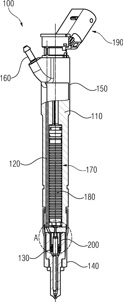
[0018] figure 1 A partial sectional view of a piezoelectric injector according to the invention is shown. Piezo injector 100 may be used to inject fuel into an internal combustion engine. The piezo injector 100 can be used, for example, to inject diesel in a common rail internal combustion engine.

[0019] The piezoelectric injector 100 has an injector housing 110 . The injector housing 110 may be composed of substantially any desired material, since the thermal expansion characteristics of the injector housing 110 are not critical. In particular, injector housing 110 need not be composed of Invar.

[0020] A high-pressure hole 120 is arranged in the injector housing 110 into which highly pressurized fuel can be injected through a high-pressure port. The high-pressure bore 120 extends in the longitudinal direction through the injector housing 110 to a high-pressure region 130 which will be discussed further below in the lower section 140 , namely the nozzle body of the pie...


PUM


Abstract

The invention relates to a piezo injector with an actuator chamber (170), in which a piezo actuator (180) is arranged. The piezo injector comprises an upper section, the injector body (150) and a lower section, the nozzle body (140). The piezo injector also has a control piston bore (200), which is formed in the nozzle body, wherein a control sleeve (220), in which a control piston (340) is received, is arranged in the control piston bore (200). The control sleeve (220) seals against an intermediate plate (260) with a first front face (240) facing the piezo actuator (180). The control piston (340) has a first side (360) facing the piezo actuator (180), wherein the first front face (360) of the control piston (340) and the section of the control sleeve (220) facing the piezo actuator (180) form a first control chamber (380).

Description

technical field [0001] The invention relates to a piezoelectric injector according to claim 1 . Background technique [0002] Internal combustion engines with direct fuel injection are known. For direct fuel injection, injection valves are used, for example piezo injectors, the nozzle needles of which are driven by means of piezo actuators. Here, a hydraulic injector unit is arranged between the actuator and the nozzle needle. Deflection of the actuator is translated into a corresponding deflection of the nozzle needle. For this purpose, an almost play-free coupling between the piezoelectric actuator and the nozzle needle is necessary. However, such a play-free coupling is difficult to maintain because of thermally induced changes in the length of the piezoelectric injector. If the lost motion stroke between the piezo actuator and the nozzle needle is too small, this can lead to incomplete closure of the nozzle needle. If the lost motion stroke between the piezo actuato...

Claims


Application Information

Patent Timeline
Patent Type & Authority Applications(China)
IPC IPC(8): F02M51/06
CPCF02M2200/704F02M51/0603F02M2200/708F02M2547/001F02M2200/705B05B1/3046B05B17/0607F02M47/02F02M57/02
Inventor W.许尔茨
Owner VTESCO TECH GMBH
Why Eureka
Try Eureka