Multi-stage dust remover adopting bionic vanes for improving dust removing efficiency
A dust collector and blade technology, applied in the field of environmental protection, can solve the problems of increasing dust removal power consumption and maintenance cost, small applicable dust removal range, wear of the device wall, etc., so as to reduce flue gas dust pollution, improve dust removal efficiency, and reduce operating costs. Effect
- Summary
- Abstract
- Description
- Claims
- Application Information
AI Technical Summary
Problems solved by technology
Method used
Image

Examples
specific Embodiment 1
[0035] In specific embodiment one:
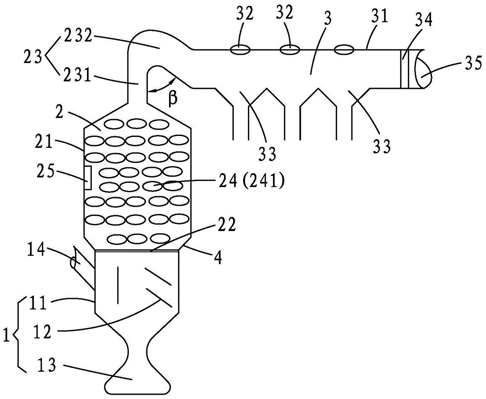
[0036] The inner diameter of the curved pipe 23 is 500 mm, the height of the straight pipe part 231 is 200 mm, and the angle β between the straight pipe part 231 and the curved pipe part 232 is 50°. The inner diameter of the air intake pipe 14 is 960 mm, and the outer diameter is 1000 mm, that is, the pipe wall thickness is 20 mm.
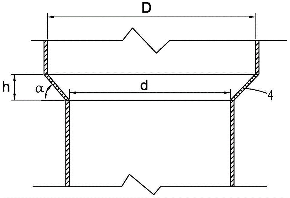
[0037] The ratio D / d of the upper and lower diameters of the inner diameter gradual expansion structure 4 is 1:1.1, the angle α of the wall surface of the inner diameter gradual expansion structure 4 is inclined relative to the horizontal plane is 30°, and the vertical height h of the inner diameter gradual expansion structure 4 is is 200mm, and the inner diameter D of the upper edge of the gradually expanding inner diameter structure 4 is 2000mm. The remaining parts are consistent with the contents of the above-mentioned specific implementation manners, so the description will not be repeated here.
specific Embodiment 2
[0038] In specific embodiment two:
[0039] The inner diameter of the curved pipe 23 is 800 mm, the height of the straight pipe part 231 is 900 mm, and the angle β between the straight pipe part 231 and the curved pipe part 232 is 87°. The inner diameter of the air intake pipe 14 is 2992mm, and the outer diameter is 3000mm, that is, the pipe wall thickness is 4mm.
[0040] The ratio D / d of the upper and lower diameters of the inner diameter gradual expansion structure 4 is 1:3, the angle α of the wall surface of the inner diameter gradual expansion structure 4 is inclined relative to the horizontal plane is 80°, and the vertical height h of the inner diameter gradual expansion structure 4 is is 700mm, and the inner diameter D of the upper edge of the gradually expanding inner diameter structure 4 is 5000mm. The remaining parts are consistent with the content of the above-mentioned specific embodiment, and will not be described again here.
specific Embodiment 3
[0041] In specific embodiment three:
[0042] The inner diameter of the curved pipe 23 is 600 mm, the height of the straight pipe part 321 is 500 mm, and the angle β between the straight pipe part 231 and the curved pipe part 232 is 75°. The inner diameter of the air intake pipe 14 is 2000mm, and the outer diameter is 2020mm, that is, the pipe wall thickness is 10mm.
[0043] The ratio D / d of the upper and lower diameters of the inner diameter gradual expansion structure 4 is 1:2, the angle α of the wall surface of the inner diameter gradual expansion structure 4 is inclined relative to the horizontal plane is 60°, and the vertical height h of the inner diameter gradual expansion structure 4 is The inner diameter D of the upper edge of the gradually expanding inner diameter structure 4 is 4000 mm. The remaining parts are consistent with the contents of the above-mentioned specific implementation manners, so the description will not be repeated here.
[0044] The dedusting pr...
PUM
| Property | Measurement | Unit |
|---|---|---|
| Height | aaaaa | aaaaa |
| The inside diameter of | aaaaa | aaaaa |
| Outer diameter | aaaaa | aaaaa |
Abstract
Description
Claims
Application Information
 - R&D
- Intellectual Property
- Life Sciences
- Materials
- Tech Scout
- Unparalleled Data Quality
- Higher Quality Content
- 60% Fewer Hallucinations
Browse by: Latest US Patents, China's latest patents, Technical Efficacy Thesaurus, Application Domain, Technology Topic, Popular Technical Reports.
© 2025 PatSnap. All rights reserved.Legal|Privacy policy|Modern Slavery Act Transparency Statement|Sitemap|About US| Contact US: help@patsnap.com