
Horizontal welding method

A technology of horizontal welding and welding points, which is applied in the direction of welding equipment, arc welding equipment, workpiece edge, etc., and can solve problems such as easy undercut and welding instability

Active Publication Date: 2015-07-29
上海气焊机厂有限公司
View PDF5 Cites 7 Cited by
  • Summary
  • Abstract
  • Description
  • Claims
  • Application Information

AI Technical Summary

Problems solved by technology

But this situation is prone to undercut and the welding is unstable

Method used


Image

  • Horizontal welding method
  • Horizontal welding method
  • Horizontal welding method

Examples


Embodiment Construction

[0034] In order to make the above objects, features and advantages of the present invention more comprehensible, specific implementations of the present invention will be described in detail below in conjunction with the accompanying drawings. In the following description, numerous specific details are set forth in order to provide a thorough understanding of the present invention. However, the present invention can be implemented in many other ways different from those described here, and those skilled in the art can make similar improvements without departing from the connotation of the present invention, so the present invention is not limited by the specific implementations disclosed below.

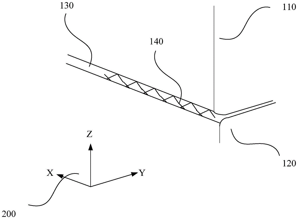
[0035] see figure 1 It is a schematic diagram of a transverse welding method according to an embodiment of the present invention. As shown in the figure, a transverse groove 130 is formed between the upper base material 110 and the lower base material 120, and a solid liner can be la...


PUM


Abstract

The invention discloses a horizontal welding method, which is used for carrying out horizontal welding on an end bevel formed between upper base metal and lower base metal and comprises the steps that a welding gun swings up and down along a preset track along the direction of surfaces of the upper base metal and the lower base metal, and advances in a reciprocating manner along the extending direction of the end bevel, so as to finish the horizontal welding of the end bevel. According to the horizontal welding method, through the arrangement of a welding preset rail, the retracement reciprocating of welding is realized, the stability of the welding is guaranteed, and a welding part which has no undercut, is excellent in weld penetration and is sound can be obtained.

Description

technical field [0001] The invention relates to the field of welding technology, in particular to a welding method for a transverse bead. Background technique [0002] Usually, the lateral position single-side welding method is for the welding groove formed by the upper base metal and the lower base metal, and the copper strap or solid ceramic material is replaced on the inner side to fix it, and the base metal and the inner lap material are surrounded. Welding is performed by feeding the electrode while supplying the shielding gas in the groove. The position of horizontal welding tends to cause the weld metal to sag due to gravity, so welding defects such as undercut or poor penetration are likely to occur on the weld bead. [0003] Under normal circumstances, a zigzag welding trajectory is adopted for the welding of the groove, but this method is often not welded firmly and is prone to false welding. For manual welding, under normal circumstances, the welder will perform...

Claims


Application Information

Patent Timeline
Patent Type & Authority Applications(China)
IPC IPC(8): B23K33/00B23K9/022
CPCB23K9/022B23K33/00B23K33/004
Inventor 不公告发明人
Owner 上海气焊机厂有限公司
Learn More