

Online arc-shaped abrasive wheel trimming device based on cup-shaped tool spherical surface envelope
A dressing device and cup-shaped technology, which is applied in the direction of abrasive surface adjustment devices, manufacturing tools, metal processing equipment, etc., can solve the problems of low dressing precision, small application range, and single function of the device, so as to improve the grinding quality and the application range Extensive, the effect of improving the grinding accuracy
- Summary
- Abstract
- Description
- Claims
- Application Information
AI Technical Summary
Problems solved by technology
Method used
Image

Examples
specific Embodiment approach 1
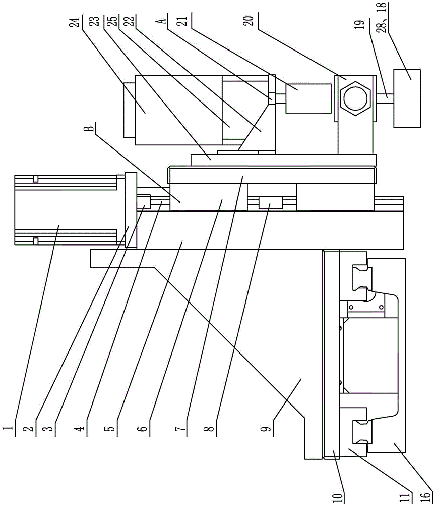
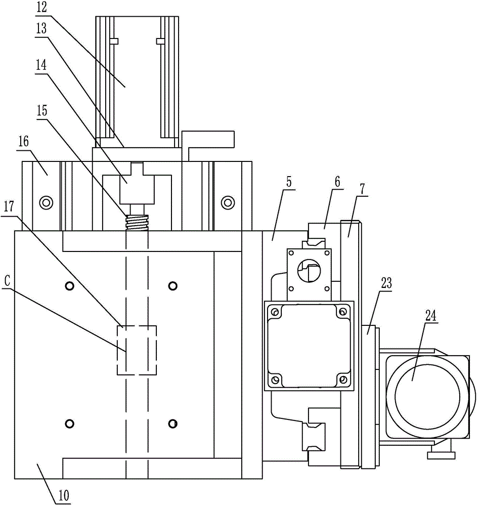
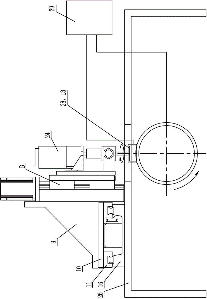
[0016] Specific implementation mode one: combine Figure 1-Figure 3 Explain, a kind of circular arc grinding wheel on-line dressing device based on cup-shaped tool spherical envelope in this embodiment includes a first stepping motor 1, a second stepping motor 12, a connecting frame 9, a horizontal connecting plate 16, a rotating mechanism A, Vertical movement mechanism B and horizontal movement mechanism C;
[0017] The output shaft of the first stepping motor 1 is vertically arranged, and the output shaft of the second stepping motor 12 is arranged horizontally; the rotating mechanism A includes a reduction motor 24 and a connecting assembly 25, and the axial direction of the reduction motor 24 is vertically arranged;
[0018] The first stepping motor 1 and the horizontal moving mechanism C are installed on the connecting frame 9, and the output shaft of the first stepping motor 1 is equipped with a vertical moving mechanism B that can move up and down on the connecting fram...
specific Embodiment approach 2
[0021] Specific implementation mode two: combination figure 1 Explain that the connection assembly 25 of this embodiment includes a connection base 22, a connection plate 23, a third coupling 21 and a shaft system 20; the vertical movement mechanism B is connected to the connection plate 23, and the connection base 22 is connected to the connection plate 23 , the geared motor 24 is installed on the connection base 22, the output end of the geared motor 24 is connected with the shaft 19 of the shaft system 20 installed on the connecting plate 23 through the third coupling 21, and the output end of the geared motor 24 is connected with the shaft 19 Coaxial arrangement, cup-shaped copper electrode 28 or cup-shaped grinding wheel 18 are installed on the shaft 19. So arranged, the rotating speed of described reduction motor 24 is converted into the cup-shaped copper electrode 28 of mechanical dressing device or the rotary motion of cup-shaped emery wheel 18 by the 3rd coupling 21, ...
specific Embodiment approach 3
[0022] Specific implementation mode three: combination figure 1 Explain that the vertical movement mechanism B of this embodiment includes a first lead screw pair, a vertical slider 6 and a vertical connecting plate 5; the vertical connecting plate 5 is installed on the connecting frame 9, and the first stepping motor 1 is installed on the On the vertical connecting plate 5, the output shaft of the first stepping motor 1 is connected with the vertically arranged first lead screw 4 of the first lead screw pair, and the first screw nut 8 of the first lead screw pair is connected with the vertical slider 6 is connected, the vertical slide block 6 is slidably installed on the vertical connecting plate 5, and the connecting plate 23 is connected with the vertical slide block 6. Set in this way, the rotating speed of the first stepper motor 1 is transformed into a displacement in the vertical direction through the first lead screw 4, the first screw nut 8, the vertical slider 6 and ...
PUM
 Abstract
Description
Claims
Application Information