Plastic product fusion joining process and fusion joining device thereof

A technology of plastic products and welding, applied in the field of plastics, can solve the problems of high manufacturing cost, high production cost and lack of market competitiveness of injection molding equipment.

Inactive Publication Date: 2015-07-29
左世月 +1
View PDF0 Cites 1 Cited by
  • Summary
  • Abstract
  • Description
  • Claims
  • Application Information

AI Technical Summary

Problems solved by technology

[0005] Integral injection molding, this process adopts the integral injection molding process, through the design of a complete set of wire reel molds, the entire wire reel is injection molded in place through the injection molding machine, the biggest defect of this production process is the high production cost, the production of injection molding equipment The manufacturing cost is high, and the production cost of each coil is 3-5 times that of the bolt fixing process, which does not have market competitiveness

Method used


Image

  • Plastic product fusion joining process and fusion joining device thereof
  • Plastic product fusion joining process and fusion joining device thereof
  • Plastic product fusion joining process and fusion joining device thereof

Examples


Embodiment 1

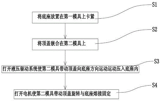
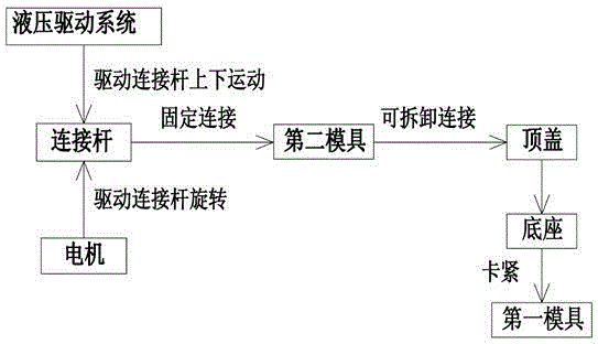
[0026] Embodiment 1: as Figure 1 to Figure 3 As shown, the technical scheme adopted by the present invention is as follows: a welding process for plastic products, comprising the following steps:

[0027] S1. Place the base 2 on the first mold 3 and clamp it tightly;

[0028] S2. Embedding the top cover 1 on the second mold 6, so that the base 2 and the top cover 1 are arranged opposite to each other;

[0029] S3. Turn on the hydraulic drive system to make the second mold 6 drive the top cover 1 to move towards the base 2, and press it into the base 2;

[0030] S4. Turn on the motor to make the second mold 6 drive the top cover 1 to rotate relative to the base, so that the top cover 1 and the base 1 are welded and fixed.

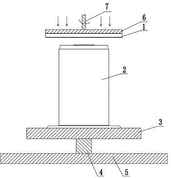
[0031] The base 2 in step S1 includes a supporting base 23, a base body 24, a first welding ring surface 21 and a first rib 22, wherein the supporting base 23 is a plate-like structure, and the base body 24 is fixedly arranged on the supporting ba...

Embodiment 2

[0037] Embodiment 2: as Figure 4 to Figure 6 As shown, it is the second embodiment of the present invention. The difference between this embodiment and Embodiment 1 is that first ribs are arranged at intervals on the first welding ring surface and the second welding ring surface of Embodiment 1 respectively. 22 and the second rib 13, the first rib 22 and the second rib 13 are strip-shaped structures, and their material is consistent with the material of the top cover and the base, and is integrally injection molded with the top cover and the base, the first rib 22 and the second ribs 13 are arranged at even intervals along the periphery of the first welding ring surface and the second welding ring surface respectively. When welding, the top cover is pressed into the base, and the first ribs and the second ribs are alternately arranged. Two adjacent first ribs 22 and second ribs 13 are engaged with each other. When the motor drives the top cover to rotate, the first ribs 22 an...


PUM


Abstract

The invention discloses a plastic product fusion joining process which comprises the following steps of: S1 placing a base on a first mold, and tightly clamping; S2 embedding a top cover into a second mold, so that the base and the top cover are correspondingly arranged in an opposite direction; S3 turning on a hydraulic driving system, so that the top cover is driven to move to the base by the second mold and is pressed into the base; S4 turning on a motor, so that the top cover is driven to rotate relative to the base by the second mold, and the top cover is in fixed fusion joining with the base. A plastic product fusion joining device comprises the first mold, a support shaft, the base, the second mold, a connecting rod, the hydraulic driving system and the motor, wherein the first mold is arranged on the base through the support shaft, and the base is fixedly clamped on the first mold. The plastic product fusion joining process and the plastic product fusion joining device have the advantages of less working procedures, low production cost, high assembly precision, large bearing capacity of a produced wire coil and high production efficiency.

Description

technical field [0001] The invention relates to the field of plastics, in particular to a welding process and welding device for plastic products used in the manufacture of wire reels. Background technique [0002] The wire reel was first used for machine cabling and turnover of wires and cables. With the development of various industries, the application field of the wire reel has gradually expanded, but it is mainly used for the packaging container of the corresponding product. It has become a An indispensable accessory product for winding and storing wires, cables and more. With the development of the plastic industry, the strength and hardness of plastics have been generally improved. Therefore, plastic reels have gradually become the mainstream reel structure due to their light weight and high strength. The existing manufacturing processes for plastic reels include three types: [0003] Glue bonding process, this production process produces an I-shaped plastic reel, th...

Claims


Application Information

Patent Timeline
IPC IPC(8): B29C65/06
Inventor 左世月苟举才
Owner 左世月
Why Eureka
Try Eureka