Rodless hydraulic transmission oil pumping system

A hydraulic transmission and oil pumping technology, applied in the field of petroleum development and exploration, can solve the problems of complex structure, unsatisfactory cost and efficiency, and large maintenance workload of hydraulic piston pump, and achieve a simple structure, wide application range and low loss. Effect

Inactive Publication Date: 2015-07-29
汤洪
View PDF6 Cites 4 Cited by
  • Summary
  • Abstract
  • Description
  • Claims
  • Application Information

AI Technical Summary

Problems solved by technology

[0003] However, the structure of this hydraulic piston pump is very complicated, the equipment cost is high, the maintenance workload is heavy, and the operating cost is high, resulting in unsatisfactory cost and efficiency.
In specific applications, the commonly used oil production equipment also includes electric submersible pumps, downhole drive screw pumps, surface drive screw pumps, oil pumping units, sucker rod pumps, and triple pumping oil production equipment, etc., but these equipments generally have high operating costs, Defects such as large maintenance work

Method used


Image

  • Rodless hydraulic transmission oil pumping system
  • Rodless hydraulic transmission oil pumping system
  • Rodless hydraulic transmission oil pumping system

Examples


Embodiment Construction

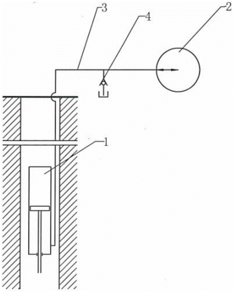
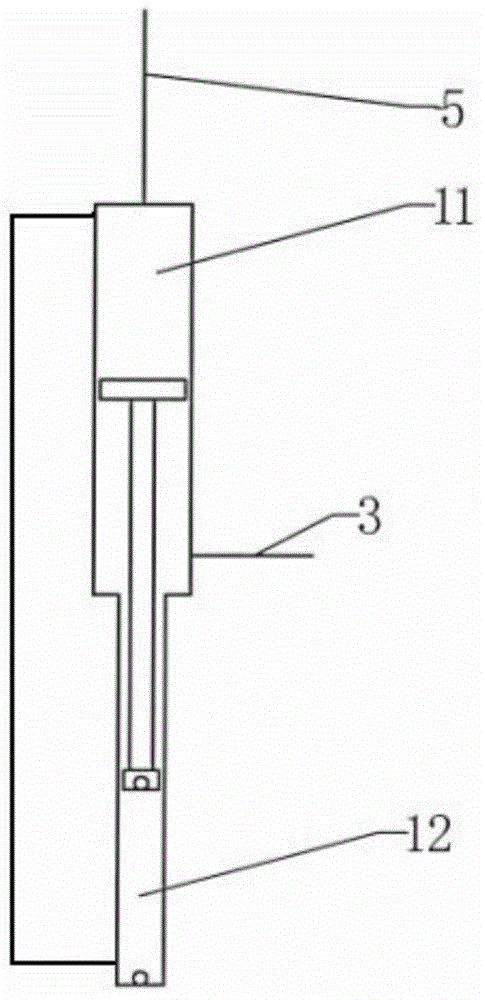
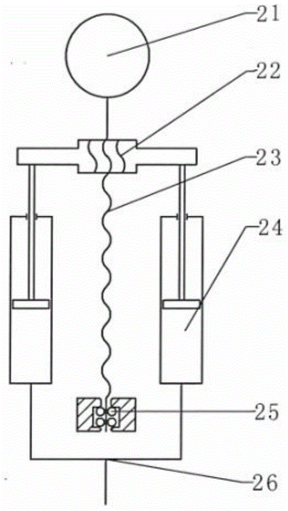
[0029] see Figure 1 to Figure 6 , shows the rodless hydraulic transmission pumping system of the present invention.

[0030] see figure 1 , simply shows the basic structure of the whole rodless hydraulic transmission oil pumping system of the present invention. A brand-new hydraulic transmission oil production method is introduced, which mainly replaces the sucker rod in the prior art through hydraulic pipelines, and uses the up and down reciprocating flow of liquid to transmit the reciprocating motion to the underground.

[0031] In order to realize the hydraulic transmission of the present invention, the rodless hydraulic transmission oil pumping system includes a hydraulic cylinder 1 and a hydraulic pump 2, and the hydraulic cylinder 1 is arranged between the tail pipe 9 in the oil extraction string and the production oil pipe 5 that supplies oil to the outside of the well, The hydraulic pump 2 is connected to the hydraulic cylinder 1 through a hydraulic pipeline 3 to fo...


PUM


Abstract

The invention discloses a rodless hydraulic transmission oil pumping system. The rodless hydraulic transmission oil pumping system comprises a hydraulic cylinder located at the underground and a hydraulic pump located at the ground; the hydraulic cylinder is arranged in the place with required depth in an oil pumping pipe pillar; the hydraulic pump is connected to the hydraulic cylinder through the hydraulic pipeline, and the hydraulic pump is the hydraulic pump for alternating sucking and discharging fluid at divided period; a fluid inlet and a fluid discharge opening are combined into one; the upper end of the hydraulic cylinder is connected to a production oil pipe, and the lower end is connected to a tail pipe; the middle part of the hydraulic cylinder is further provided with a piston rod driven by the hydraulic pump, the hydraulic pipeline transmits the fluid with alternative change in discharge and suction by the hydraulic pump to the underground hydraulic cylinder in the form of reciprocating motion; a piston in the hydraulic cylinder performs vertical reciprocating movement, and the hydraulic transmission oil exploration between the tail pipe and the production oil pipe is realized; therefore, the rodless hydraulic transmission oil pumping system is simple in structure, the fluid pipeline connection is more direct, the loop is effectively simplified, and efficiency is higher, and loss is less; the transmission is more controllable, the maintenance is convenient, and application scale is wide; besides, the pumping efficiency is greatly improved.

Description

technical field [0001] The invention relates to the technical field of oil development and exploration, in particular to a rodless hydraulic transmission oil pumping system. Background technique [0002] The hydraulic piston pump is a kind of hydraulic transmission oil pumping equipment that has been used in the field in the prior art. Specifically, the hydraulic piston pump transmits the hydraulic power to the downhole drive cylinder by the surface pump, and then the drive cylinder is controlled by a reversing valve , and drives the oil well pump plunger to reciprocate up and down. The surface pump in the prior art is usually realized by a plunger pump. This type of plunger pump has a short stroke and a high stroke frequency, and can continuously provide power fluid in the same flow direction downhole. The reversing valve is used to alternately inject the power fluid into the upper and lower chambers of the driving cylinder through the reversing valve, so as to realize the...

Claims


Application Information

Patent Timeline
Patent Type & Authority Applications(China)
IPC IPC(8): F04B47/00E21B43/00
Inventor 汤洪
Owner 汤洪
Why Eureka
Try Eureka