A digital display flowmeter with a pressure measuring tube display for experimental teaching and its measurement method

A pressure measuring tube and flowmeter technology, which is applied in the field of experimental measurement, can solve the problems of automatic exhaust of multiple pressure measuring tubes, short circuit of gas circuit, low or even close to atmospheric pressure, etc., and achieves the effect of good teaching effect.

Active Publication Date: 2018-01-05
ZHEJIANG UNIV +1
View PDF10 Cites 0 Cited by
  • Summary
  • Abstract
  • Description
  • Claims
  • Application Information

AI Technical Summary

Problems solved by technology

[0007] However, in order to combine the traditional row-type piezometric tube with the high-precision differential pressure flowmeter suitable for low-flow measurement as mentioned above, and integrate it into a complete set of on-site measurement and control innovative experimental equipment, there are still many problems to be solved, such as Real-time zeroing problem, automatic exhaust problem of multiple pressure measuring tubes
[0008] Real-time zero adjustment problem: Like this kind of electrical measuring instrument, it is often necessary to verify the zero point in real time. For example, after the electronic scale is weighed, the zero point can be verified by removing the weight, and the zero point of this instrument is quite stable
This is because the pressure at the measuring point of each piezometric tube is different, and the pressure at the measuring point of some piezometric tubes is very low, even close to atmospheric pressure. The air flow from the pressure measuring port of one or several pressure measuring tubes will cause a short circuit in the gas circuit, and the pressure on the main channel of the gas circuit will drop suddenly, causing the other pressure measuring tubes to be unable to drain water, so the simultaneous exhaust will not be achieved. Effect

Method used


Image

  • A digital display flowmeter with a pressure measuring tube display for experimental teaching and its measurement method

Examples


Embodiment Construction

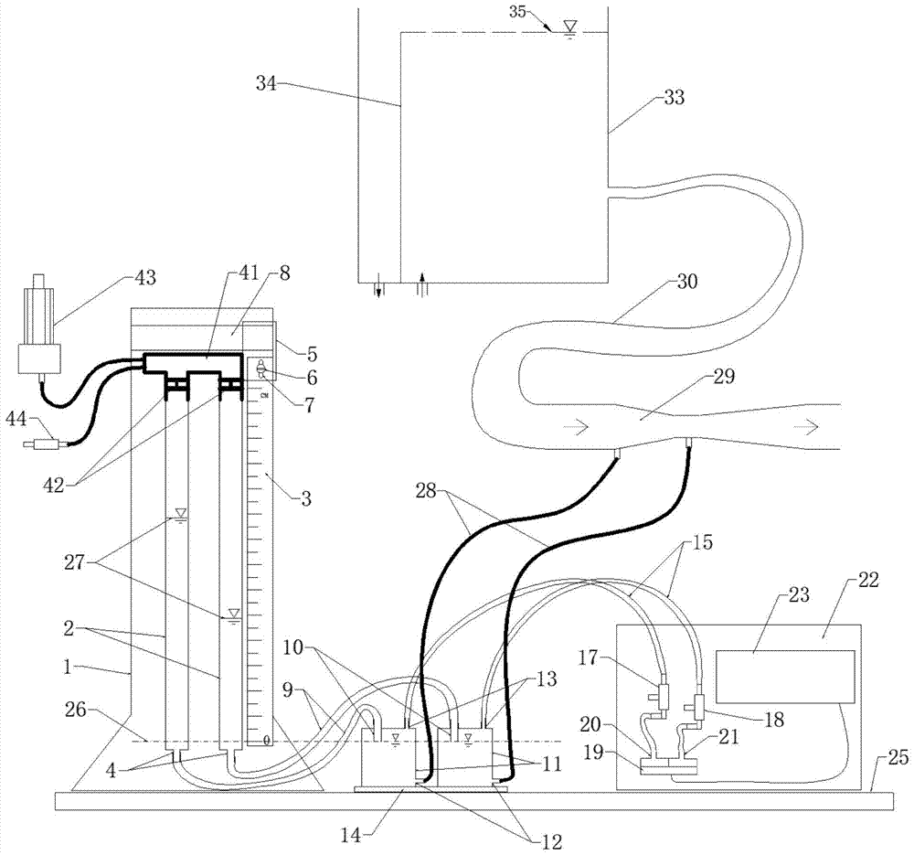
[0055] as attached figure 1 As shown, it is a digital display flowmeter with a piezometric tube display for experimental teaching of the present invention, including: a differential pressure flow signal generator 29 for generating a differential pressure signal, and a differential pressure flow signal generator 29 with a There are two pressure measurement points; two sets of pressure measurement components, each group of pressure measurement components includes a pressure measurement cylinder 11, each pressure measurement cylinder 11 is provided with a water inlet 12 at the bottom, and a connecting positioning tube 10 at the top, which is connected with the positioning tube 10 connected to the pressure measuring tube 2; two groups of pressure measuring components are respectively connected to the two pressure measuring points of the differential pressure flow signal generator 29 through the water inlet 12 of the lower part of the pressure measuring cylinder 11 respectively; Tw...


PUM


Abstract

The invention discloses a digital display flowmeter with a pressure measuring tube display for experimental teaching and a measuring method, comprising: a differential pressure flow signal generator for generating differential pressure signals; two sets of pressure measuring components, each set of pressure measuring components The assembly includes a pressure measuring cylinder, a connecting positioning tube and a pressure measuring tube; a pressure sensor used to detect the pressure difference of compressed air in the two pressure measuring cylinders; a microcomputer digital display meter used to convert the pressure signal detected by the pressure sensor into a flow rate ; A fixed bracket for the pressure measuring tube; a scale scale for calibrating the liquid level in the pressure measuring tube. The device and method of the present invention comprehensively and innovatively use the principle of fluid mechanics to solve the problem of experimental measurement and display, and combine the traditional pressure measuring tube and modern measurement technology, with high precision and high display, and can be widely used in fluid Among the mechanical experiment teaching instruments, it can stimulate students' interest in learning and inspire students' innovation consciousness, which is beneficial to the cultivation of innovation ability and has a good teaching effect.

Description

technical field [0001] The invention relates to the field of experimental measurement, in particular to a digital display flowmeter with a pressure measuring tube display for experimental teaching and a measuring method. Background technique [0002] Hydraulics and Fluid Mechanics is a major professional basic course for many majors in engineering colleges. Modern hydraulics is based on the three pillars of experiment, theory and calculation. Therefore, experiment is an indispensable content in the teaching process. [0003] Among them, the small flow, small pressure difference, and high-precision digital display flow measurement device for small pipeline water flow used in experimental teaching is currently in a blank state. Taking the small desktop hydrodynamics hydraulics teaching instrument as an example, since its diameter is usually less than 30mm and the flow rate is 5-300ml / s, the flow rate is often very small. Traditionally, the gravimetric method or the volumetric...

Claims


Application Information

Patent Timeline
Patent Type & Authority Patents(China)
IPC IPC(8): G01F1/34G09B23/12
Inventor 毛欣炜毛根海李聪
Owner ZHEJIANG UNIV
Why Eureka
Try Eureka