Magnetic-flux-gate current sensor

A current sensor, fluxgate technology, applied in voltage/current isolation, measuring current/voltage, instruments, etc., can solve problems such as poor accuracy

Inactive Publication Date: 2015-07-29
HEBEI UNIV OF TECH
View PDF11 Cites 19 Cited by
  • Summary
  • Abstract
  • Description
  • Claims
  • Application Information

AI Technical Summary

Problems solved by technology

[0004] The technical problem to be solved by the present invention is to provide a fluxgate current sensor, which is a fluxgate current sensor with a magnetic flux gathering shell and an orthogonal distribution of windings, which eliminates the coupling between the windings, and introduces a magnetic flux gathering shell to gather The

Method used


Image

  • Magnetic-flux-gate current sensor
  • Magnetic-flux-gate current sensor
  • Magnetic-flux-gate current sensor

Examples


Embodiment 1

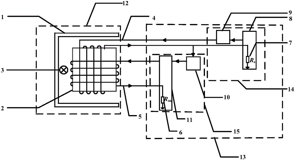
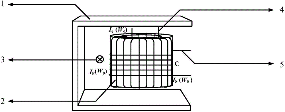
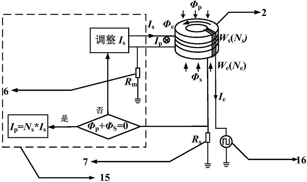
[0050] according to figure 1 , figure 2 , Figure 4 and Figure 5 The illustrated embodiment constitutes the fluxgate current sensor of this embodiment, which is a fluxgate current sensor with a magnetization shell 1 and windings distributed orthogonally, including a fluxgate detection probe 12 and a signal processing circuit 13; Among them, the fluxgate detection probe 12 is composed of a magnetic gathering shell 1 plus a ring magnetic core 2 and an exciting winding 4 plus a secondary feedback winding 5. The ring magnetic core 2 is placed inside the magnetic gathering shell 1, and the exciting winding 4 is a wire. The winding formed on the annular magnetic core 2 is uniformly wound along the radial direction of the annular magnetic core 2, and the secondary feedback winding 5 is a winding formed by winding uniformly along the circumferential direction of the annular magnetic core 2 after the excitation winding 4 is wound. Signal processing circuit 13 is divided into excit...

Embodiment 2

[0052] Except that the excitation winding 4 is a winding formed by uniformly winding 125 turns of a wire on the annular magnetic core 2 along the radial direction of the annular magnetic core 2, the secondary feedback winding 5 is formed along the annular magnetic core after the excitation winding is wound. Except for the winding formed by uniform winding of 225 turns in the circumferential direction, the others are the same as in Embodiment 1.

Embodiment 3

[0054] Except that the excitation winding 4 is a winding formed by uniformly winding 150 turns of a wire on the annular magnetic core 2 along the radial direction of the annular magnetic core 2, the secondary feedback winding 5 is formed along the annular magnetic core after the excitation winding is wound. Except for the winding formed by uniform winding of 250 turns in the circumferential direction, the others are the same as in Embodiment 1.


PUM

PropertyMeasurementUnit
Resistivityaaaaaaaaaa
Curie pointaaaaaaaaaa
Saturation magnetic inductionaaaaaaaaaa

Abstract

The invention discloses a magnetic-flux-gate current sensor, and relates to a device used for measuring current. The magnetic-flux-gate current sensor is provided with a magnetism gathering shell and adopts winding orthogonal distribution, and comprises a magnetic-flux-gate detecting probe and a signal processing circuit, wherein the magnetic-flux-gate detecting probe consists of a magnetic core with an annular magnetic core, and an excitation winding with a secondary feedback winding; the signal processing circuit is divided into two parts, namely an exciting circuit and a zero flux detecting circuit; the exciting circuit part further comprises an exciting signal generating circuit and a signal driving circuit; the zero flux detecting circuit part further comprises two parts, namely an integrating comparator circuit and an H-bridge driving circuit. According to the magnetic-flux-gate current sensor, the coupling among windings is eliminated; meanwhile, the magnetism gathering shell is introduced, effective magnetic fields are gathered, and the influence caused by surrounding stray magnetic fields is shielded; the defect of poorer accuracy of a current measurement result caused by a greater output error of the existing magnetic-flux-gate current sensor generated in actual measurement is overcome; the measurement sensitivity is further improved.

Description

technical field [0001] The technical solution of the present invention relates to a device for measuring current, specifically a fluxgate current sensor. Background technique [0002] With the development of power electronics technology, the demand for high-performance current sensors is increasing day by day, and more and more current sensors have also entered the research scope of researchers. Traditional current detection devices include shunts, current transformers, Rogowski coils and Hall sensors; existing new current detection devices include fluxgate current sensors, giant magnetoresistance effect current sensors and optical fiber sensors. Due to its simple principle and convenient control, the Hall sensor is currently the most widely used in engineering applications. However, the Hall sensor has the disadvantages of low sensitivity to magnetic fields, and relatively large temperature drift and zero drift. The fluxgate current sensor has the characteristics of unique...

Claims


Application Information

Patent Timeline
IPC IPC(8): G01R19/00G01R15/00G01R15/18
Inventor 杨晓光郭伟李元园李丛丛朱波
Owner HEBEI UNIV OF TECH
Why Eureka
Try Eureka