Dead-time compensation method and system of open-loop driver

An open-loop driver and dead-time compensation technology, which is applied to output power conversion devices, electrical components, and AC power input to DC power output. Distortion and other problems, to avoid the problem of zero current clamping, reduce jitter and noise, and reduce interference

Active Publication Date: 2015-07-29
SHANGHAI STEP ELECTRIC +1
View PDF1 Cites 4 Cited by
  • Summary
  • Abstract
  • Description
  • Claims
  • Application Information

AI Technical Summary

Problems solved by technology

However, it is difficult to accurately detect the current direction during zero current ride through
Incorrect current direction judgment will affect the effect of dead zone compensation, or even worsen the effect, resulting in output voltage distortion, motor speed jitter and other problems

Method used


Image

  • Dead-time compensation method and system of open-loop driver
  • Dead-time compensation method and system of open-loop driver
  • Dead-time compensation method and system of open-loop driver

Examples


Embodiment Construction

[0023] In order to make the object, technical solution and advantages of the present invention clearer, various embodiments of the present invention will be described in detail below in conjunction with the accompanying drawings. However, those of ordinary skill in the art can understand that, in each implementation manner of the present invention, many technical details are provided for readers to better understand the present application. However, even without these technical details and various changes and modifications based on the following implementation modes, the technical solution claimed in each claim of the present application can be realized.

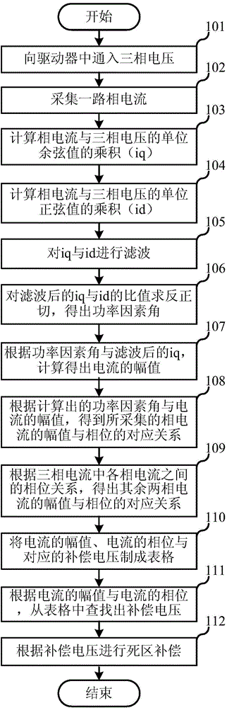
[0024] The first embodiment of the present invention relates to a dead zone compensation method of an open-loop driver, the specific process is as follows figure 1 shown, including the following steps:

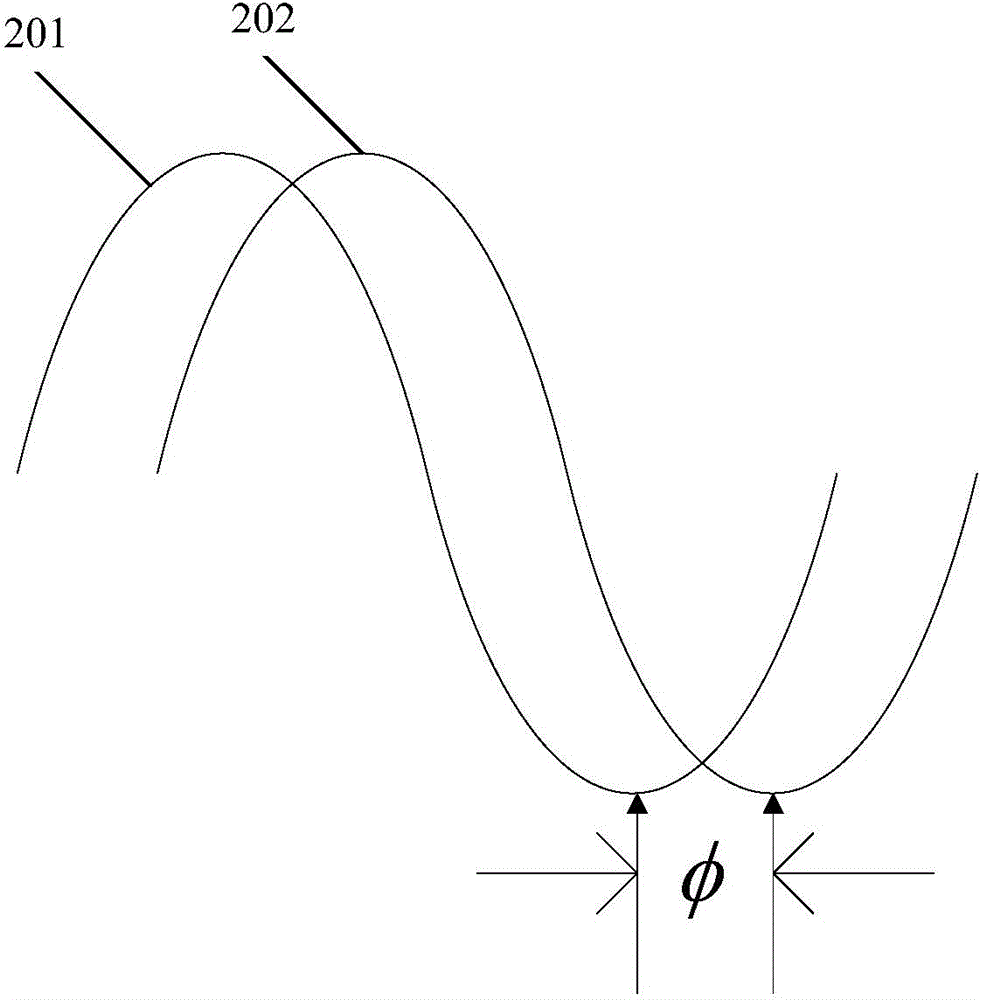
[0025] In step 101, three-phase voltages (Va, Vb, Vc) are applied to the driver. Among them, the phase difference among ...


PUM


Abstract

The invention relates to the technical field of alternating-current servo frequency converter and discloses a dead-time compensation method and system of an open-loop driver. The method includes: calculating the power factor angle of the voltage and currents in the driver and the amplitude of the currents; performing online current setting according to the amplitude and power factor angle of the currents to obtain the correspondence of the amplitude and the phase of the currents; performing dead-time compensation according to the correspondence; wherein the magnitude of compensation voltage is acquired according to the amplitude of the currents, and the positive and negative of the compensation voltage are judged according to the phase of the corresponding currents. By the method, current direction can be judged accurately, interference on dead-time compensation is reduced, and the precision of the output voltage is increased; zero current clamping problem caused by the incorrect current direction judging can be avoided, system jittering and noises are reduced, control precision is increased, and system low-speed performance is improved.

Description

technical field [0001] The invention relates to the technical field of AC servo frequency converters, in particular to a dead zone compensation method and system for an open-loop driver. Background technique [0002] Open-loop control of servo drives is widely used. Especially in the low-speed area, high-precision voltage output is a very important indicator. The main circuit of the inverter power supply such as the driver is a bridge circuit composed of switching devices. The bridge circuit generally adopts the method of pulse width modulation (such as svpwm, that is, space vector pulse width modulation) for control, that is, the devices of the upper and lower bridge arms are turned on in turn to realize the control of voltage and current. Due to the time delay of the device, and in order to avoid the device damage caused by the simultaneous conduction of the devices of the upper and lower bridge arms, in various pulse width modulated frequency conversion power supplies, ...

Claims


Application Information

Patent Timeline
Patent Type & Authority Applications(China)
IPC IPC(8): H02M7/5387
Inventor 胡跃进丁信忠严彩忠刘伟东李虎修柳竹青
Owner SHANGHAI STEP ELECTRIC
Why Eureka
Try Eureka