Conveying pipe sleeve for pumping concrete construction

A technology for pumping concrete and conveying pipes, applied in the field of conveying pipe sleeves, which can solve the problems of cumbersome heat preservation methods and poor heat preservation effects of conveying pipes, and achieve the effects of simple structure, convenient disassembly and assembly, and prevention of pipe clogging

Active Publication Date: 2015-08-05
张鑫浩
View PDF6 Cites 8 Cited by
  • Summary
  • Abstract
  • Description
  • Claims
  • Application Information

AI Technical Summary

Problems solved by technology

[0003] The technical problem to be solved by the present invention is that the existing heat preservation method of the conveyin

Method used


Image

  • Conveying pipe sleeve for pumping concrete construction
  • Conveying pipe sleeve for pumping concrete construction

Examples


Example Embodiment

[0032] The present invention will be further described below with reference to the drawings and embodiments.

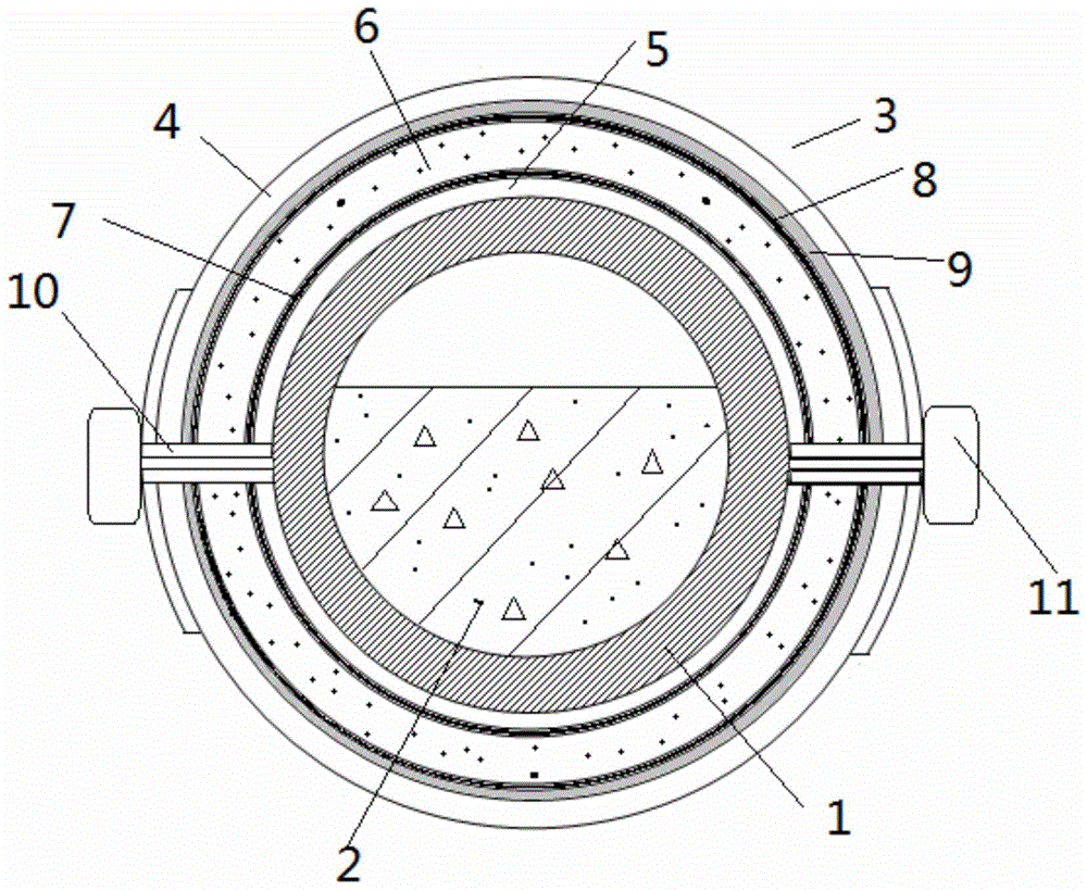
[0033] Such as figure 1 , figure 2 As shown, a conveying pipe sleeve 3 for pumping concrete construction is sleeved on the outside of the conveying pipe 1 of the pumping concrete 2, and the inner diameter of the pipe sleeve 3 is compatible with the outer diameter of the conveying pipe 1. , So that the pipe sleeve 3 can be sleeved outside the conveying pipe 1; along the length of the conveying pipe 1, the pipe sleeve 3 is formed by splicing multiple pipe sleeve units. Each pipe sleeve unit is formed by splicing more than two pipe piece units, and each pipe piece unit is a sealed cavity composed of an outer wall 4, an inner wall 5, an upper bottom surface, a lower bottom surface, and two side sealing plates 10. The closed cavity is filled with a phase change material 6, which is an organic phase change material or an inorganic phase change material. The filling amount o...


PUM


Abstract

The invention relates to a conveying pipe sleeve for a pumping concrete construction. The conveying pipe sleeve is in cup joint at the outer side of a conveying pipe (1), and is spliced by multiple sections of pipe sleeve units in a length direction of the conveying pipe; each section of the pipe sleeve unit is spliced by more than two pipe piece units; the pipe piece units are sealed cavities consisting of outer walls (4), inner walls (5), upper bottom surfaces, lower bottom surfaces and two side sealing plates (10); phase change materials (6) are filled in the sealed cavities; electric heating devices (7) are arranged at the inner sides of the inner walls, and temperature sensors connected with temperature control devices of the electric heating devices are embedded at the outer sides; and the inner sides of the outer walls are provided with reflective film layers (8) and heat insulating layers (9) in sequence from top to bottom. The multiple pipe piece units are clamped and fastened on the outer surface of the conveying pipe through connecting parts (11); the multiple sections of the pipe sleeve units are longitudinally spliced; and the upper and lower bottom surfaces of the adjacent pipe piece units are respectively provided with concave parts (12) and convex parts (13) with matched shapes. The pipe sleeve is simple in structure and convenient to be disassembled, prevents the blockage caused by low temperature, and improves the energy utilization rate.

Description

technical field [0001] The invention relates to the field of building construction, in particular to a delivery pipe sleeve for pumping concrete construction. Background technique [0002] In the field of building construction, pumping concrete has been widely used. The normal pumped concrete forms a columnar fluid in the center of the pipe, which is in a suspended state when flowing. The surface is covered with a layer of cement slurry, which acts as a lubricant in contact with the pipe wall, and there is basically no relative movement between the aggregates. When the movement of some coarse aggregates is blocked, the moving speed of the following aggregates is affected by it and slows down, resulting in the formation of coarse aggregates, while the nearby mortar is squeezed away, and the remaining gaps are filled with fine aggregates, and the cement slurry is lubricated. The layer is destroyed, the movement resistance increases, and the speed slows down until the movement...

Claims


Application Information

Patent Timeline
IPC IPC(8): E04G21/04
Inventor 张鑫浩杨涛涛
Owner 张鑫浩
Why Eureka
Try Eureka