Mounting structure of auxiliary engine

An installation structure and engine technology, applied in the direction of engine components, machines/engines, valve devices, etc., can solve problems such as weight increase and cost increase, and achieve the effect of avoiding weight increase

Inactive Publication Date: 2015-08-05
SUZUKI MOTOR CORP
View PDF6 Cites 2 Cited by
  • Summary
  • Abstract
  • Description
  • Claims
  • Application Information

AI Technical Summary

Problems solved by technology

In this case, a large driving torque for driving the high-pressure fuel pump acts on the camshaft, which may increase the weight and cost of the camshaft for improving the strength.

Method used


Image

  • Mounting structure of auxiliary engine
  • Mounting structure of auxiliary engine
  • Mounting structure of auxiliary engine

Examples


Embodiment Construction

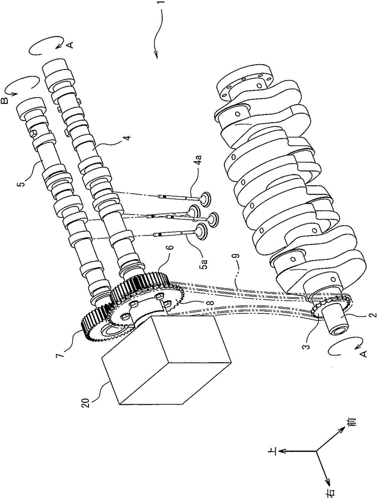
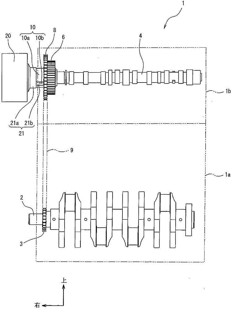
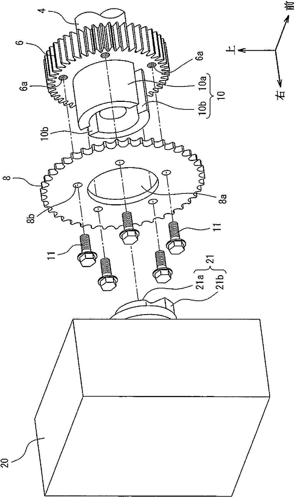
[0026] The details of the attachment structure of the engine auxiliary machine according to the embodiment of the present invention will be described below with reference to the drawings. Figure 1 to Figure 4 It is a figure which shows the attachment structure of the engine auxiliary machine which concerns on embodiment of this invention.

[0027] First, the configuration will be described. exist figure 1 , figure 2 Among them, an auxiliary engine 20 is installed in the engine 1 , and the auxiliary engine 20 is driven by power generated by the engine 1 . In the present embodiment, the auxiliary engine 20 is a high-pressure fuel pump for pressurizing fuel to a fuel injector (not shown) or a vacuum pump for generating negative pressure.

[0028] The engine 1 is an inline 4-cylinder DOHC (Double OverHead Camshaft: double overhead camshaft) type engine, and is arranged transversely at the front of a vehicle (not shown). Here, in this embodiment, the arrows shown together wi...


PUM


Abstract

The invention provides a mounting structure of an auxiliary engine, which can prevent weight increase and manufacture process complication and furthermore allows mounting of the auxiliary engine in an engine. An exhaust cam gear (6) is fixed at one end of an exhaust cam shaft (4). Additionally, at one end side of the exhaust cam shaft (4), a cam sprocket is arranged in the exhaust cam gear (6) in an integral rotation manner. Furthermore, the combined part (10) of the exhaust cam gear (6) is combined with the combined part (21) of the auxiliary engine (20), thereby transmitting power from the exhaust cam gear (6) to the auxiliary engine (20). Additionally, the exhaust cam gear (6) is provided with a boss part (10a). Furthermore the auxiliary engine (20) is provided with an input shaft (21a). Furthermore, the boss part (10a) is provided with a snapping trough (10b) in the axial direction. Furthermore a clamping projection (21b) is formed at the outer peripheral part of the input shaft (21a).

Description

technical field [0001] The present invention relates to an attachment structure of an engine auxiliary machine in which an engine auxiliary machine is mounted on an engine and the engine auxiliary machine is driven by the engine. Background technique [0002] In general, a high-pressure fuel pump mounted on a direct-injection gasoline engine or a diesel engine drives a plunger through a pump cam formed at one end of a camshaft to boost fuel pressure. In this case, since a large driving torque for driving the high-pressure fuel pump acts on the camshaft, the weight of the camshaft for improving the strength may increase and the cost may increase. [0003] In this regard, conventionally, there is known a mounting structure for engine auxiliary machinery in which a pump camshaft for driving a high-pressure fuel pump is arranged coaxially inside a crankshaft, and a pump sprocket ( Refer to Patent Document 1). In the mounting structure of the conventional engine auxiliary machi...

Claims


Application Information

Patent Timeline
Patent Type & Authority Applications(China)
IPC IPC(8): F02M37/06
CPCF02M39/02F01L1/022F01L1/026
Inventor 桧垣知幸
Owner SUZUKI MOTOR CORP
Why Eureka
Try Eureka