Intelligent energy-saving air handling system for operation room

A technology of air handling system and air handling unit, which is applied in air conditioning system, application, household heating, etc. It can solve the problems of low utilization rate of Class I surgery, non-adjustable clean room, high operating cost, etc., and achieve easy control of product quality , The height of the technical ceiling is reduced and the air leakage rate is low

Inactive Publication Date: 2015-08-05
殷晓冬
View PDF8 Cites 15 Cited by
  • Summary
  • Abstract
  • Description
  • Claims
  • Application Information

AI Technical Summary

Problems solved by technology

To achieve this, a good air treatment system must be configured for the operating room. The traditional air treatment system is generally a primary return air system, and the circulation unit is mainly responsible for the cold, heat and humidity loads in the clean room. Therefore, in summer and transitional seasons, in order to meet the indoor According to the dehumidification requirements, the entire circulating air volume needs to be treated to a low temperature of about 13°C. Then, in order to ensure the indoor temperature, the air needs to be reheated by electric heating to reach the supply air temperature. There is a huge cold and heat in this process. Offset situation, resulting in serious energy waste
[0003] In addition, the current clean operating rooms and other related clean rooms in hospitals are designed to be used in accordance with the cleanliness level of the original design, and cannot be adjusted to clean rooms of other levels.
The utilization rate of Class I operations in Class I clean operating rooms in many hospitals is not high, and most of the time they are used as low-level operating rooms, which wastes a lot of operating costs

Method used


Image

  • Intelligent energy-saving air handling system for operation room
  • Intelligent energy-saving air handling system for operation room
  • Intelligent energy-saving air handling system for operation room

Examples


Embodiment Construction

[0036] The present invention / invention will be described in further detail below in conjunction with the accompanying drawings, so that those skilled in the art can implement it with reference to the description.

[0037] It should be understood that terms such as "having", "comprising" and "including" as used herein do not entail the presence or addition of one or more other elements or combinations thereof.

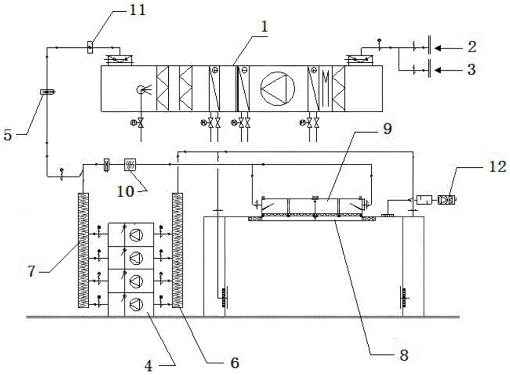
[0038] combine Figure 1 to Figure 3 As shown, it is an energy-saving air treatment system for an intelligent operating room according to the present invention, which includes the following parts connected in sequence through air ducts,

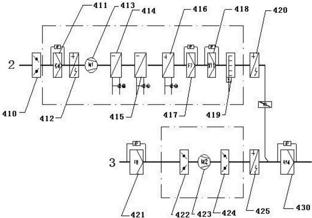
[0039] Air handling unit 1, used to filter outdoor fresh air 2 and indoor fresh air 3;

[0040] The electric heating unit 5 is an air duct type electric heater, and the electric heating unit 5 is arranged on the output pipeline of the air outlet from the air handling unit 1, and is used for electrically heating the output air; and,

...


PUM


Abstract

The invention discloses an intelligent energy-saving air handling system for an operation room. The intelligent energy-saving air handling system comprises an air handling unit (1), an electric heating unit (5) and a noise elimination static pressure tank group which are sequentially connected through an air pipe, the air handling unit (1) is used for filtering outdoor fresh air (2) and indoor fresh air (3), the electric heating unit (5) is an air duct type electric heater and arranged on an outlet air output pipeline of the air handling unit (1) and used for electrically heating outputted air, the noise elimination static pressure tank group includes a first noise elimination static pressure tank (6) and a second noise elimination static pressure tank (7) which are connected by a plurality of circulating fan (4) parallel pipelines, and the electrically heated fresh air and return air subjected to noise elimination by the noise elimination static pressure tank group are mixed by a three-way valve, heated, sterilized and inputted to the operation room through an air supply static pressure tank (9) arranged at the top of the intelligent operation room. According to the intelligent energy-saving air handling system for the operation room, energy is saved by more than 50%.

Description

technical field [0001] The invention relates to an air treatment system. More specifically, the present invention relates to an energy-saving air treatment system for an intelligent operating room. Background technique [0002] With the development of medical technology and the improvement of people's demand for medical conditions, the requirements for the cleanliness of medical operating rooms are getting higher and higher. Environmental parameters. To achieve this, a good air treatment system must be configured for the operating room. The traditional air treatment system is generally a primary return air system, and the circulation unit is mainly responsible for the cold, heat and humidity loads in the clean room. Therefore, in summer and transitional seasons, in order to meet the indoor According to the dehumidification requirements, the entire circulating air volume needs to be treated to a low temperature of about 13°C. Then, in order to ensure the indoor temperature,...

Claims


Application Information

Patent Timeline
Patent Type & Authority Applications(China)
IPC IPC(8): F24F3/00F24F3/16F24F13/02F24F13/24F24F13/068F24F13/28
CPCF24F3/00F24F3/16F24F13/02F24F13/068F24F13/24F24F13/28F24F2013/242F24F8/10
Inventor 殷晓冬姜伟康姜皓遐曾海川
Owner 殷晓冬
Why Eureka
Try Eureka