Eureka AIR delivers breakthrough ideas for toughest innovation challenges, trusted by R&D personnel around the world.

Cooling system for power battery of new-energy bus and new-energy bus

A power battery and cooling system technology, which is applied in the arrangement of the cooling combination of the power unit, power unit, secondary battery, etc., can solve the problems of being in a cooling state, endangering the safety of passengers, and intensifying combustion with oxygen-enriched air, so as to ensure the safety of passengers Effects of improving safety and reliability

Active Publication Date: 2015-08-05
HUBEI JINQUAN NEW MATERIALS CO LTD
View PDF6 Cites 13 Cited by
  • Summary
  • Abstract
  • Description
  • Claims
  • Application Information

AI Technical Summary

Problems solved by technology

However, using the low-temperature air in the compartment to cool the power battery has the following disadvantages: (1) In order to ensure the heat dissipation effect of the power battery, the flow rate of low-temperature air used for cooling is required to be large, and the low-temperature air in the compartment can be used in a short period of time. The interior will be evacuated, and the temperature of the outside supplementary air entering the compartment is high, so that the temperature in the compartment cannot achieve the expected effect, so that the air conditioner is always in a cooling state, resulting in increased energy consumption, and sometimes even the full load cooling of the air conditioner cannot meet the requirements. cabin temperature requirements
(2) The inside of the battery box is connected to the atmosphere. Moisture and dust in the air will enter the battery box and adhere to the surface of the power battery. Long-term use will cause the heat dissipation effect of the power battery to deteriorate, and the insulation between the main circuit of the battery and the shell Poor performance, the electrical connection inside the battery pack is susceptible to corrosion, etc., reducing the reliability of the power battery
(3) Once the battery accidentally burns, the oxygen-enriched air sent from the compartment will intensify the combustion, and at the same time, the toxic gas will flow backward into the air-conditioning system in the compartment, directly endangering the safety of passengers

Method used


Image

  • Cooling system for power battery of new-energy bus and new-energy bus
  • Cooling system for power battery of new-energy bus and new-energy bus
  • Cooling system for power battery of new-energy bus and new-energy bus

Examples


Embodiment 1

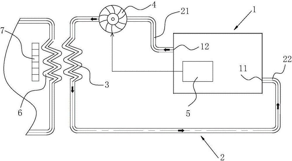
[0039] Such as figure 1 As shown, a power battery cooling system for a new energy bus includes a battery box 1 and a circulating air duct 2 communicating with the battery box 1. The battery box 1 and the circulating air duct 2 form a closed cavity, and the cavity is filled with There is a cooling medium, and the circulating air duct 2 is provided with a radiator 3 for heat exchange. The radiator 3 is installed on the side away from the battery box 1, and the radiator 3 is arranged close to the evaporator 6 of the external air conditioning system. The circulating air A driving fan 4 is arranged on the road 2 and between the battery box 1 and the radiator 3 . In this embodiment, the driving fan 4 is installed between the air outlet 12 and the radiator 3 . The radiator 3 is arranged on the leeward side of the evaporator 6 of the external air conditioning system. Specifically, the normal-temperature air passes through the evaporator 6 of the external air-conditioning system to fo...

Embodiment 2

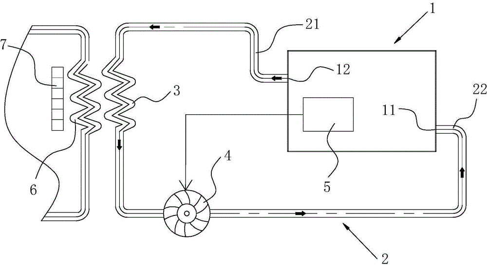
[0046] The difference between this embodiment and Embodiment 1 is:

[0047] Such as figure 2 As shown, the driving fan 4 is installed between the air inlet 11 and the radiator 3, and the cooling medium is neon gas.

Embodiment 3

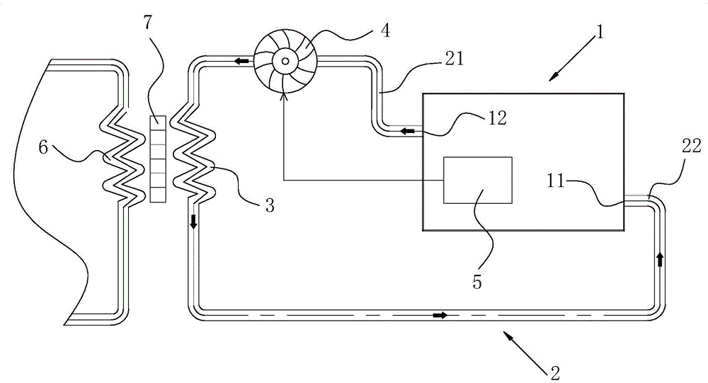
[0049] The difference between this embodiment and Embodiment 1 is:

[0050] Such as image 3 As shown, the evaporator 6 is arranged on the windward side of the axial flow fan 7, the radiator 3 is arranged on the side of the axial flow fan 7 away from the evaporator 6, and the cooling medium is argon.


PUM


Abstract

The invention discloses a cooling system for a power battery of a new-energy bus. The cooling system comprises a battery box and a circulating air passage communicated with the battery box. The battery box and the circulating air passage form an enclosed cavity which is filled with a cooling medium; the circulating air passage is provided with a radiator used for heat exchange; the radiator is arranged to abut against an evaporator of an external air-conditioning system; and a driving blower fan is arranged on the circulating air passage and between the battery box and the radiator. The power battery cooling system enables the interior of the battery box to be isolated from external air; thus, on the one hand, moisture and dust in the air are prevented from entering the interior of the battery box, thereby improving reliability; and on the other hand, external air is prevented from aggravating combustion of the power battery in the case of accidental combustion of the power battery and gas produced after combustion is prevented from back-discharging into a compartment, thereby guaranteeing safety of passengers. The invention also discloses the new-energy bus. Since the power battery cooling system isolated from external air is employed, driving reliability and security of the new-energy bus are improved.

Description

technical field [0001] The invention relates to the technical field of new energy passenger cars, in particular to a power battery cooling system of a new energy passenger car and the new energy passenger car. Background technique [0002] New energy buses have the advantages of low pollution, low noise, and linear power output. The above characteristics make new energy buses more and more popular. At present, new energy buses are more and more widely used in the field of urban public transportation, and we can see more and more new energy buses running in every corner of the city. Electric buses are a major new energy bus. Although electric buses have broad prospects, there are still many shortcomings in current electric buses. [0003] The cooling of the power battery of an electric bus is generally by sending the air with a lower temperature in the compartment into the battery box, so that the low-temperature air flows through the surface of the power battery, so that th...

Claims


Application Information

Patent Timeline
Patent Type & Authority Applications(China)
IPC IPC(8): H01M10/613H01M10/625H01M10/6563B60K11/06
CPCY02E60/10
Inventor 朱锦其谢小梅李华文李芬戴贤青
Owner HUBEI JINQUAN NEW MATERIALS CO LTD
Why Eureka
Eureka Blog
Learn More