
Cleaning system for filter sand layer

A cleaning system and a technology for filtering sand layers, applied in the field of cleaning systems, can solve the problems of larger engineering scale and higher operating costs, and achieve the effects of miniaturizing equipment, preventing screen clogging, and reducing engineering scale and operating costs.

Active Publication Date: 2016-11-23
HITACHI ZOSEN CORP +1
View PDF8 Cites 0 Cited by
  • Summary
  • Abstract
  • Description
  • Claims
  • Application Information

AI Technical Summary

Problems solved by technology

Therefore, the cleaning equipment is enlarged, the project scale is enlarged, and the operating cost is also increased.

Method used


Image

  • Cleaning system for filter sand layer
  • Cleaning system for filter sand layer
  • Cleaning system for filter sand layer

Examples


Embodiment

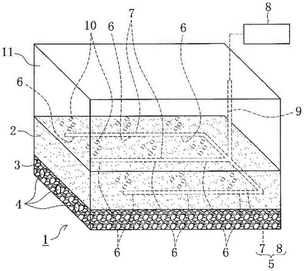
[0031] exist figure 1 Among them, 1 is the seawater infiltration water intake equipment, which absorbs the seawater permeated into the filter sand layer 2 and the support gravel layer 3 arranged on the seabed through the water intake pipe 4 buried in the support gravel layer 3 . The water intake pipe 4 is a pipe with a water intake hole, and is connected with a sump pump to obtain water from the seawater permeating into the filter sand layer 2 and the supporting gravel layer 3 .

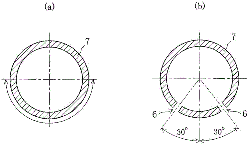
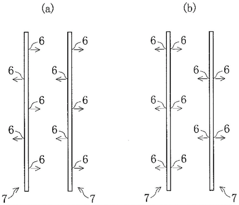
[0032] 5 is the cleaning system of the present invention, which is composed of an air diffuser pipe 7 embedded in the filter sand layer 2 and having an air injection hole 6, and a compressed air delivery device 8 that sends air to the air diffuser pipe 7. The cleaning system removes the filter sand The suspended matter caused by the blockage of the mesh of layer 2 is cleaned.

[0033] In this embodiment, a plurality of diffuser pipes 7 are arranged and embedded in the horizontal direction. Each dif...


PUM


Abstract

To reduce the size, scale of construction, and running cost of an apparatus for cleaning a sand filtration layer. A cleaning system which removes clogging sediments from a sand filtration layer 2, used with an apparatus for an infiltration intake of seawater which performs a seawater intake, by means of a water intake pipe 4 buried in the supporting gravel layer 3, after the seawater has been infiltrated through the sand filtration layer 2 and a supporting gravel layer 3 on an ocean floor. This cleaning system is provided with a diffuser pipe 7 having blow holes 6, and which is buried in the supporting gravel layer 3, as well as a compressed air delivery device 8 for feeding an air into the diffuser pipe 7. The system operates by blowing the air from the blow holes 6 to agitate the filtration sand of the sand filtration layer 2, to remove the sediments which have become trapped in or accumulated on the sand filtration layer 2. The system can achieve a smaller size, a smaller scale of construction, and a lower running cost than a conventional system which injects fresh water or seawater into the sand filtration layer.

Description

technical field [0001] The present invention relates to a cleaning system for a filter sand layer, which removes suspended substances that cause mesh clogging from the filter sand layer of a seawater infiltration water intake facility installed on the seabed. Background technique [0002] For example, in a seawater desalination plant, in order to obtain clean seawater with less impurities, a supporting gravel layer and a filter sand layer are installed on the seabed, and the seawater infiltrating into these layers is taken from the seawater infiltrating through the water intake pipe buried in the supporting gravel layer. Water intake equipment (for example, the patent document 1 figure 1 ). [0003] If the osmosis water intake method implemented using this seawater osmosis water intake device continues to draw water, suspended substances such as sediment and plankton (hereinafter simply referred to as "suspended substances") that cause the mesh clogging of the filter sand l...

Claims


Application Information

Patent Timeline
Patent Type & Authority Patents(China)
IPC IPC(8): B01D24/46B01D29/66E03B3/04
CPCB01D24/4631B01D24/4636B01D2101/04B01D2201/084B01D2201/087
Inventor 乾真规新里英幸井上隆之柳本洋一大岩忠男三村等
Owner HITACHI ZOSEN CORP
Learn More