SCS steel-concrete deck slab with U-shaped connecting structures inside

A steel plate concrete and connection structure technology, applied in the direction of bridges, bridge parts, bridge materials, etc., can solve the problems of restricting the structure and size of the lower supporting pier, the development and application restrictions of concrete bridge decks, and the cracks of concrete bridge decks, etc. Achieve the effect of low construction cost, good connection effect and light weight

Inactive Publication Date: 2015-08-12
CHANGAN UNIV
View PDF7 Cites 2 Cited by
  • Summary
  • Abstract
  • Description
  • Claims
  • Application Information

AI Technical Summary

Problems solved by technology

In the actual use process, the concrete bridge deck has the following defects: first, the self-heavy weight limits the structure and size of the lower supporting pier; Steel structure load-bearing girders such as steel box girders) are connected, but the connection performance between the steel structure and the concrete is poor, so a large number of shear connectors are needed, and the amount of steel is large; third, due to the perennial dynamic load, the bridge deck The top and bottom of the concrete bridge deck are most affected, and the bottom of the concrete bridge deck is prone to cracks, which eventually lead to the failure of the concrete bridge deck
Due to the above reasons, the development and application of concrete bridge decks are limited.

Method used


Image

  • SCS steel-concrete deck slab with U-shaped connecting structures inside
  • SCS steel-concrete deck slab with U-shaped connecting structures inside

Examples


Embodiment Construction

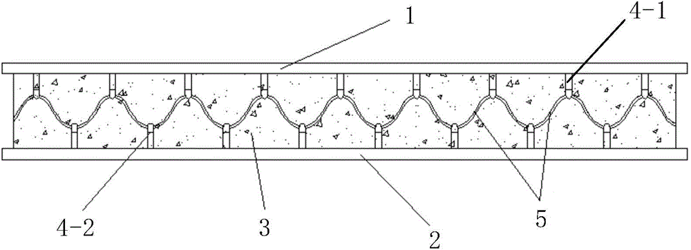
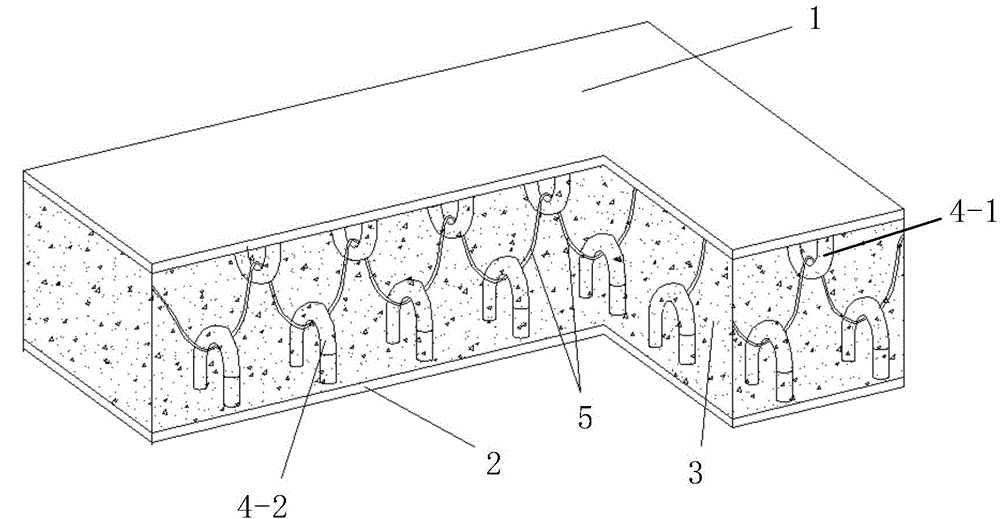
[0034] Such as figure 1 , figure 2 As shown, the present invention includes a bridge deck bottom plate 2, a bridge deck top plate 1 arranged directly above the bridge deck bottom plate 2 and arranged in parallel with the bridge deck bottom plate 2, and N columns are arranged on the bridge deck top plate from left to right along the transverse bridge direction 1 and the U-shaped connection structure between the bridge deck bottom plate 2 and the inter-slab concrete structure 3 formed by pouring concrete between the bridge deck top plate 1 and the bridge deck bottom plate 2, the bridge deck top plate 1 and the bridge deck bottom plate 2 All are horizontal plates. The U-shaped connection structures in the N columns are all poured in the inter-slab concrete structure 3, and the bridge deck top plate 1 and the bridge deck bottom plate 2 are fastened and connected with the U-shaped connection structures in the N columns through the inter-slab concrete structure 3; Wherein, N is a...


PUM


Abstract

The invention discloses an SCS steel-concrete deck slab with U-shaped connecting structures inside. The SCS steel-concrete deck slab comprises a deck slab bottom plate, a deck slab top plate, N rows of U-shaped connecting structures and an inter-plate concrete structure, and the inter-plate concrete structure is formed by pouring concrete poured between the deck slab top plate and the deck slab bottom plate. The N rows of U-shaped connecting structures are all poured in the inter-plate concrete structure. Each row of U-shaped connecting structures comprises a top plate connecting structure, a bottom plate connecting structure and a connecting cable, each top plate connecting structure comprises a plurality of upper U-shaped connecting pieces distributed at the bottom of the deck slab top plate from front to back along a longitudinal bridge, each bottom plate connecting structure comprises a plurality of lower U-shaped connecting pieces distributed on the upper portion of the deck slab bottom plate from front to back along the longitudinal bridge, and the connecting cables penetrate through the inner sides of the upper U-shaped connecting pieces and the inner sides of the lower U-shaped connecting pieces from front to back. The SCS steel-concrete deck slab is simple in structure, reasonable in design, convenient to construct, good in use effect and good in mechanical property, and multiple problems of an existing concrete deck slab can be solved.

Description

technical field [0001] The invention relates to a bridge deck, in particular to an SCS steel plate concrete bridge deck with a built-in U-shaped connection structure. Background technique [0002] Steel plate sandwich concrete (steel-concrete-steel, referred to as SCS) composite structure, also known as SCS steel plate concrete structure, is a steel-concrete composite structure formed by two steel plates and concrete poured in the interlayer between the two steel plates. Because steel and concrete make up for each other's weaknesses and give full play to each other's strengths, the SCS steel plate concrete structure has high bearing capacity and excellent mechanical properties. Therefore, SCS steel plate concrete structures will be more and more widely used in structures such as offshore platforms and long-span, heavy-duty, and light bridges. [0003] At present, most of the bridge decks used are concrete bridge decks. In the actual use process, the concrete bridge deck ha...

Claims


Application Information

Patent Timeline
Patent Type & Authority Applications(China)
IPC IPC(8): E01D19/12
CPCE01D19/125E01D2101/268
Inventor 高小育陈沿辰刘永健刘永超
Owner CHANGAN UNIV
Why Eureka
Try Eureka