

A urea solution injector
A technology of injector and solution, applied in machine/engine, muffler, engine components, etc., can solve the problem of different key parts, and achieve the effect of inhibiting crystallization, reducing frictional resistance, and avoiding motion stagnation
- Summary
- Abstract
- Description
- Claims
- Application Information
AI Technical Summary
Problems solved by technology
Method used
Image

Examples
Embodiment Construction
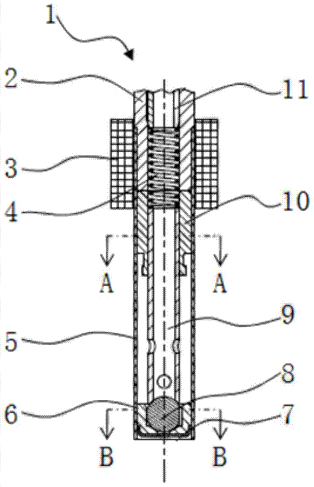
[0021] figure 1 Describe a urea solution injector 1 of a urea solution injector, including a fixed iron core 2, an electromagnetic coil 3, a spring 4, a valve sleeve 5, a valve seat 6, an orifice plate 7, a ball head 8, a valve stem 9, and an armature 10 Wait.
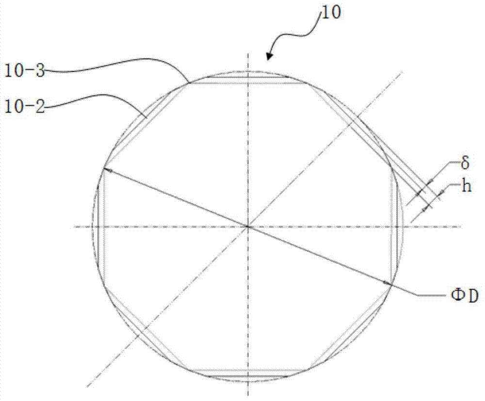
[0022] according to figure 2 , image 3 , Figure 4 , Figure 5 , describing the characteristic structure, heat resistance measures and coating measures of the armature structure of the urea solution injector.
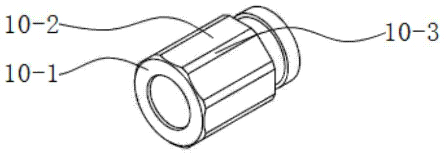
[0023] The guide outer cylinder 10-3 of the armature 10 is processed with evenly distributed multi-faceted parts 10-2, wherein the depth of the cut flat is less than the chord height of the regular octagon inscribed on the circumference of the armature. According to an advantageous structure, figure 2 The multifaceted part 10-2 shown is preferably half of the chord height, and is placed in a thin-walled valve sleeve. The wall thickness of the valve sleeve is preferably 0.3mm, thereby weakening the magnet...
PUM
 Abstract
Description
Claims
Application Information