Composite-material plate joint

A composite material board and composite material technology, applied in the field of joints of composite material boards, can solve problems such as complex and changeable application forms, difficult processing and manufacturing, and complex design technology, and achieve simple and flexible implementation, good versatility, and simple and reliable technology Effect

Inactive Publication Date: 2015-08-12
NANJING UNIV OF AERONAUTICS & ASTRONAUTICS
View PDF5 Cites 5 Cited by
  • Summary
  • Abstract
  • Description
  • Claims
  • Application Information

AI Technical Summary

Problems solved by technology

[0004] The purpose of the present invention is: in order to overcome the complex design process, difficult processing and manufacturing, insufficient flexibility and inability to adapt to complex and changeable application forms in the prior art, the present invention provides a simple and flexible implementation process. Composite plate joints that are changeable, convenient for on-site construction and repeated disassembly

Method used


Image

  • Composite-material plate joint
  • Composite-material plate joint
  • Composite-material plate joint

Examples


Embodiment 1

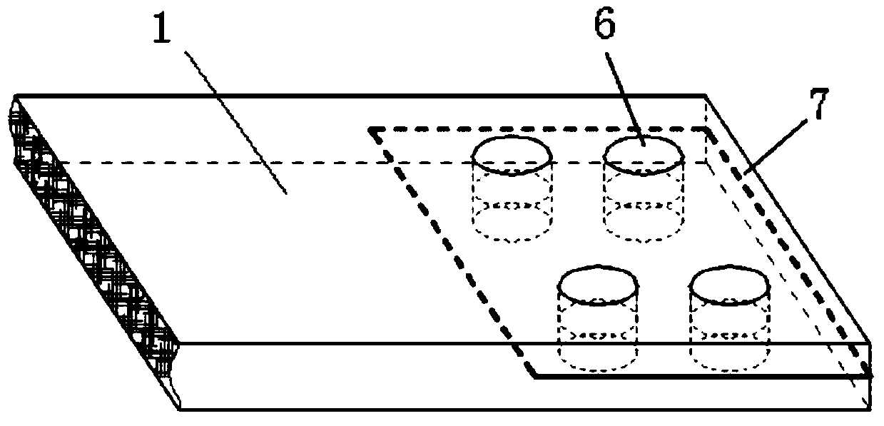
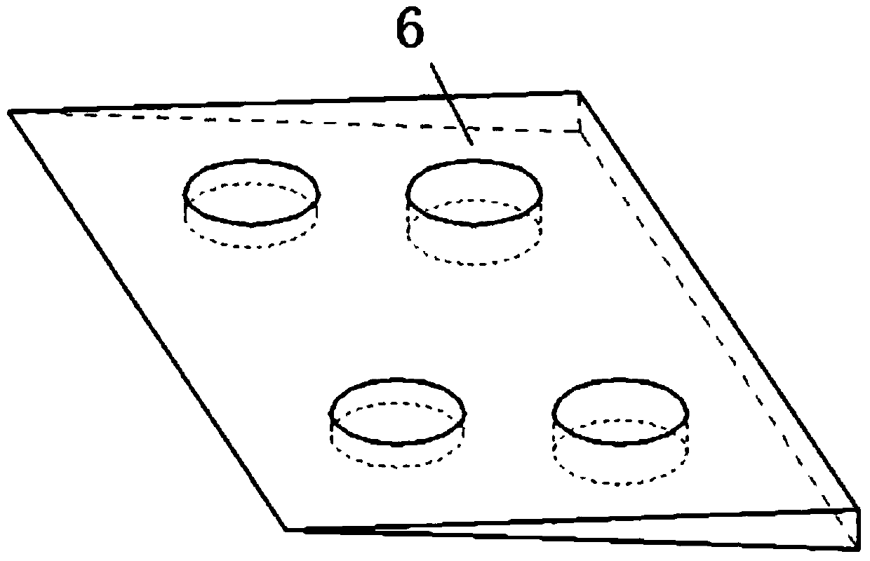
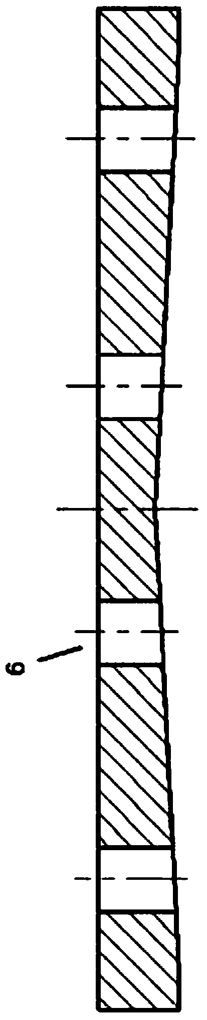
[0033] like figure 1 , figure 2 , image 3 As shown, a group of connecting holes 6 are processed on the end of the composite material plate 1, the metal wedge 2 and the connecting plate 3 by machining, and the positions of the connecting holes 6 correspond to each other for the fixed connection of the bolt 4; A slit 7 is processed along the edge of the composite material plate 1. Since the slit 7 is very narrow, it has little effect on weakening the tensile strength of the composite material plate 1, so it can meet the design requirements. A metal wedge 2 with a symmetrical slope is processed, the width of which is the same as that of the composite material plate 1 , and the length is shorter than the depth of the gap 7 on the composite material plate 1 . In addition, two identical connecting plates 3 are processed, and two symmetrical slopes are processed on one surface of the connecting plate 3, and the overall structure forms a V shape, the slope of which is consistent w...

Embodiment 2

[0037] like Figure 6 As shown, the metal wedge 2 is processed into a cross shape by mechanical processing, and the connecting plate 3 is correspondingly processed into an angle shape, and the slope of the surface that is clamped with the composite material plate 1 and the slope of the metal wedge 2 are guaranteed. unanimous. As described in the method in Embodiment 1, the connection holes 6 are processed at the corresponding positions of the end of the composite material plate 1, the metal wedge 2 and the connecting plate 3, for the fixed connection of the bolt 4; and along the edge of the composite material plate 1 A gap 7 is processed for wedging the metal wedge 2; wherein the cross-shaped metal wedge 2 has a symmetrical slope and the width is the same as that of the composite material plate 1 .

[0038] In the processed gap 7 of the composite material plate 1, and on the wedge surface of the cross-shaped metal wedge 2, evenly coat the adhesive, and then wedge the metal we...

Embodiment 3

[0040] like Figure 7 As shown, for a composite material panel 1 with a thickness of more than 10 mm, a group of symmetrical gaps 7 are processed along the end edge of the panel, and the method in Example 1 is used at the end of the composite material panel 1, the metal wedge 2 The connection hole 6 is processed at the corresponding position of the connection plate 3, which is used for the fixed connection of the bolt 4.

[0041] A metal wedge 2 with a symmetrical slope is processed, the width of which is the same as that of the composite material plate 1 , and the length is shorter than the depth of the gap 7 on the composite material plate 1 . In addition, two identical connecting plates 3 are processed. Two symmetrical slopes are processed on one surface of the connecting plate 3. The overall structure forms a V shape, the length is three times the length of the metal wedge 2, and the width is the same as that of the composite material plate 1. Same width.

[0042] In the p...


PUM


Abstract

Disclosed in the invention is a composite-material plate joint comprising a composite-material plate, a metal wedge block, and connecting plates. Connecting holes are formed in corresponding parts of the end portion of the composite-material plate, the metal wedge block, and the connecting plate. A gap is processed in the edge of the composite-material plate; and the metal wedge block is wedged into the gap. One side, has the same gradient as the metal wedge block, of each connecting plate is buckled at each of the two sides of the composite-material plate; and the connecting plates and the composite-material plate wedged into the metal wedge block are fixedly connected by bolts and nuts. The composite-material plate joint has the following advantages: the joint can be applied to connection between the composite-material plates with different materials and different heights and between the composite-material plate and other metal components and has high universality, economy, and adaptability. Moreover, the process is simple; the implementation is flexible; the mounting and dismounting become convenient; and the tensile strength is high and the structure is safe and reliable.

Description

technical field [0001] The invention relates to a composite material plate joint, which uses metal wedges as the technical core, and connects the connecting plate, composite material plates and metal wedges through bolts, providing a simple implementation process, high reliability, The utility model relates to a composite material plate joint which is convenient for on-site construction and repeated disassembly and assembly, and belongs to the field of connectors. Background technique [0002] Composite material sheets, mainly referring to carbon fiber and glass fiber reinforced resin-based composite materials, have been commercially produced in large quantities, but due to the characteristics of composite materials, it is not suitable to directly adopt the mechanical processing connection methods usually used for metal sheets, such as threaded connection, welding, etc. Therefore, it is difficult to directly obtain the joints of composite material plates required for complex...

Claims


Application Information

Patent Timeline
Patent Type & Authority Applications(China)
IPC IPC(8): F16B5/00F16B5/02
CPCF16B5/0291
Inventor 杨德华李开宇
Owner NANJING UNIV OF AERONAUTICS & ASTRONAUTICS
Why Eureka
Try Eureka