Composite stiffness damping shock absorber

A technology of compound stiffness and shock absorber, applied in shock absorber, shock absorber-spring combination, shock absorber, etc., can solve problems such as limitation and stiffness short circuit

Active Publication Date: 2015-08-12
江苏欣捷诺环境工程技术有限公司
View PDF7 Cites 7 Cited by
  • Summary
  • Abstract
  • Description
  • Claims
  • Application Information

AI Technical Summary

Problems solved by technology

[0005] The vibration isolator disclosed in the "Composite Damping Vibration Isolator" with the application number ZL85 1 03709 Chinese patent has applied the Coulomb damping structure, although it is said that it can "make the vibration isolation system properly obtain Appropriate damping, providing good isolation in the directions of the three coordinate axes, and effectively limiting the resonance amplitude", but due to the limitation of its structural characteristics, it cannot meet the requirements of maintaining stable stiffness and damping under small vibration loads to ensure good isolation. The use requirements of the vibration effect, at the same time, there will be a risk of stiffness short circuit when the vibration is large

Method used


Image

  • Composite stiffness damping shock absorber
  • Composite stiffness damping shock absorber

Examples


Embodiment 1

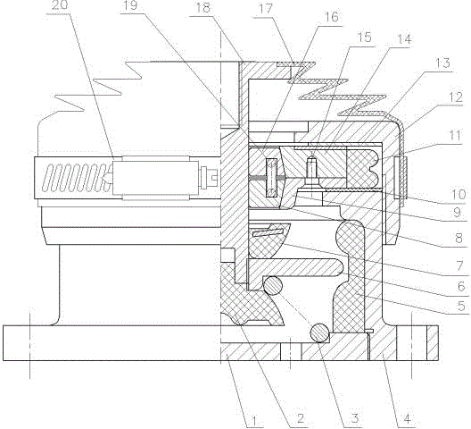
[0023] The composite stiffness damping shock absorber of the present embodiment is as figure 1 As shown, it includes a central axis 18 inserted in the center of the box-shaped base 4 . The upper end of the ring body of the base 1 extends inward to form a top surface with a central through hole, and the upper outer circle of the ring body has an external thread for screwing and fixing the upper cover 12 . The lower end of the base 1 is fixed to the bottom plate 1 by internal threads. Between the flange at the top of the central shaft 18 and the upper cover 12 is a retractable corrugated dust cover 17 fixed by a throat clamp 20 . The upper part of the central shaft 18 is equipped with a Coulomb damper axially constrained between the upper surface of the top plate of the base 4 and the lower surface of the upper cover 12 . The upper and lower friction plates 13 and 10 are respectively lined between the upper and lower end faces of the Coulomb damper and the upper surface of the...

Embodiment 2

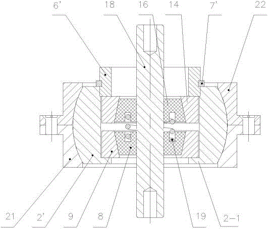
[0031]The basic structure of the composite stiffness damping shock absorber of this embodiment is the same as that of Embodiment 1, the difference is that the upper and lower cone mounting seats 14, 9 of the Coulomb damper are located in the ball seat of the ball hinge structure, and the ball seat is composed of The inner spherical concave is composed of the upper shell 22 and the lower shell 21 and the ball 2' which forms a spherical hinge structure with the upper and lower shells. The center of the ball has an internal thread hole for installing the cone mounting seat. The internal thread One end of the hole has an axial limit shoulder 2-1. The upper and lower cone mounts 14 and 9 have external threads, which are screwed into the internal threads of the center of the sphere 2' at the opposite positions of the large ends of the taper holes, leaving an adjustment interval between them. Position shoulder 2-1, the top surface of the upper cone mounting seat 14 is pressed and fix...


PUM


Abstract

The invention relates to a composite stiffness damping shock absorber, and belongs to the technical field of shock absorbing devices. The shock absorber comprises a center shaft inserted in the center of a box-shaped base, and a coulomb damper which is axially constrained between the upper surface of a top plate of the base and the lower surface of an upper cover fixedly connected with the base is installed on the upper portion of the center shaft; the lower end of the center shaft is supported on a bottom plate of the base through a buffering friction ring and a main spring connected in series, and an elastic buffering ring limited between the lower surface of the top plate and the upper surface of the bottom plate of the base is lined in an inner cavity of the base; a sunk part is formed in the inner wall of the elastic buffering ring, and the buffering friction ring stretches into the sunk part in the radial direction; when the center shaft transmits small-amplitude vibration, a gap exists between the buffering friction ring and the elastic buffering ring; when the center shaft transmits large-amplitude vibration or deflects, the buffering friction ring makes contact with the elastic buffering ring. The shock absorber can provide stable stiffness and damping under the small-amplitude vibration load and generate sharply increasing damping in the process of large-amplitude vibration and has a multi-direction elastic limiting function, and transition is stable.

Description

technical field [0001] The invention relates to a shock absorber, in particular to a composite stiffness damping shock absorber, which belongs to the technical field of shock absorbers. Background technique [0002] The damper is the key component of the vibration reduction device. As far as the applicant knows, the existing dampers are divided into two categories: coulomb damping and viscous damping. [0003] Coulomb damping is also called frictional damping. Its direction is always opposite to the direction of the moving speed of the object, and its size is proportional to the positive pressure. The formula is expressed as f=-μN, where μ is the coefficient of friction and N is the positive pressure. If the normal pressure is constant and the dry friction is constant, the damping can be changed by changing the normal pressure, or choosing materials with different friction coefficients or surface treatment methods. [0004] Viscous damping is the energy loss caused by the ...

Claims


Application Information

Patent Timeline
Patent Type & Authority Applications(China)
IPC IPC(8): F16F13/02
CPCF16F13/02
Inventor 陈昱辰
Owner 江苏欣捷诺环境工程技术有限公司
Why Eureka
Try Eureka