Generator collecting acoustic energy and sound sensor
A sound sensor and sound energy technology, applied in the direction of sensors, friction generators, sensor components, etc., can solve the problems of limited application range, inconvenient use of sensors, etc., and achieve the effect of reducing sound energy loss and improving sound energy utilization efficiency
- Summary
- Abstract
- Description
- Claims
- Application Information
AI Technical Summary
Problems solved by technology
Method used
Image
Examples
Embodiment 1
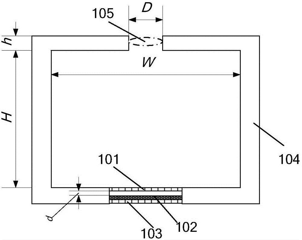
[0043] The generator of collecting sound energy of the present embodiment, see figure 1 , comprising a Helmholtz resonant cavity and a triboelectric nano-power generation component, wherein the Helmholtz resonant cavity has an opening 105, and the triboelectric nano-power generation component is a part of the outer wall 104 of the Helmholtz resonant cavity. The triboelectric nano-power generation component includes two thin films facing each other, see figure 1, the edge of the triboelectric nano-power generation component is fixed on the outer wall of the Helmholtz resonant cavity, including the first electrode layer 101, the second electrode layer 103 and the friction layer 102, wherein the inner surface of the first electrode layer 101 and the upper surface of the friction layer 102 Set face to face, the lower surface of the friction layer 102 is in contact with the second electrode layer 103; the first electrode layer 101 is an elastic material, or the whole formed by the ...
Embodiment 2
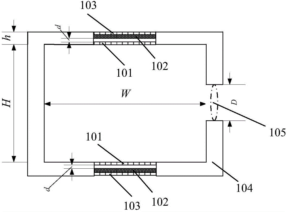
[0058] The generator of collecting sound energy of the present embodiment, see figure 2, including a Helmholtz resonant cavity and two triboelectric nano-power generating parts, wherein the Helmholtz resonant cavity has an opening 105, and the two triboelectric nano-power generating parts are part of the outer wall 104 of the Helmholtz resonant cavity, preferably, two triboelectric nano-power generating parts The power generating components are arranged on the outer walls of the two sides of the opening 105 and face to face, for example figure 2 The opening of the middle Helmholtz resonant cavity is set on the outer wall on the right side, and the two triboelectric nanometer power generation components are symmetrically set on the upper and lower outer walls of the Helmholtz resonant cavity. Same as the first embodiment, the width W, height H, opening diameter D and outer wall thickness h of the Helmholtz resonant cavity jointly determine the frequency of the response sound ...
Embodiment 3
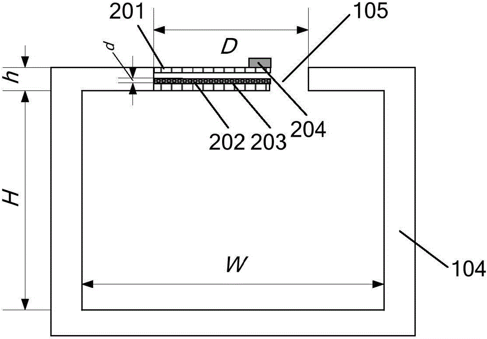
[0062] The generator of collecting sound energy of the present embodiment, see image 3 , comprising a Helmholtz resonant cavity and a triboelectric nano-power generating component, wherein the Helmholtz resonant cavity has an opening 105, and the triboelectric nano-generating component is arranged at the opening of the Helmholtz resonant cavity. The width W, height H, opening diameter D and wall thickness h of the Helmholtz resonant cavity jointly determine the frequency of the response sound wave. The structure of the triboelectric nanometer power generation part is basically the same as that of the triboelectric nanometer power generation part in Embodiment 1. The difference is that only one end of the first electrode layer, the friction layer and the second electrode layer is fixed on the outer wall of the opening 105. The free end corresponding to the fixed end makes the triboelectric nano power generation component form a generator with a cantilever arm structure. The f...
PUM
| Property | Measurement | Unit |
|---|---|---|
| Thickness | aaaaa | aaaaa |
| Thickness | aaaaa | aaaaa |
Abstract
Description
Claims
Application Information
 - R&D
- Intellectual Property
- Life Sciences
- Materials
- Tech Scout
- Unparalleled Data Quality
- Higher Quality Content
- 60% Fewer Hallucinations
Browse by: Latest US Patents, China's latest patents, Technical Efficacy Thesaurus, Application Domain, Technology Topic, Popular Technical Reports.
© 2025 PatSnap. All rights reserved.Legal|Privacy policy|Modern Slavery Act Transparency Statement|Sitemap|About US| Contact US: help@patsnap.com


