
Portable ultrasonic imaging equipment and portable ultrasonic imaging system

An ultrasonic imaging, portable technology, applied in the structure of ultrasonic/sonic/infrasound diagnostic equipment, ultrasonic/sonic/infrasound image/data processing, ultrasonic/sonic/infrasonic diagnosis, etc. and other problems, to achieve the effect of low power consumption, high integration and cost reduction

Inactive Publication Date: 2015-08-19
UNIV OF SCI & TECH OF CHINA
View PDF7 Cites 27 Cited by
  • Summary
  • Abstract
  • Description
  • Claims
  • Application Information

AI Technical Summary

Problems solved by technology

At present, the commonly used notebook-type portable ultrasound imaging system realizes the integration of imaging and display interaction, and weighs several kilograms. It is still inconvenient for doctors to carry it to the doctor, and the price is relatively expensive.
[0004] Moreover, with the aging of the population and the improvement of people's living standards, it is becoming more and more important for doctors to visit patients' homes or communities for on-site medical treatment, which puts forward higher requirements for the volume, weight and power consumption of portable ultrasound imaging systems. At the same time, it is also hoped that the image information obtained by the ultrasound imaging system can be easily known to more people (doctors or patients' family members, etc.), but the current portable ultrasound imaging equipment system cannot meet these requirements

Method used


Image

  • Portable ultrasonic imaging equipment and portable ultrasonic imaging system
  • Portable ultrasonic imaging equipment and portable ultrasonic imaging system
  • Portable ultrasonic imaging equipment and portable ultrasonic imaging system

Examples


Embodiment Construction

[0037] The technical solutions in the embodiments of the present invention are clearly and completely described below in conjunction with the accompanying drawings in the embodiments of the present invention. Obviously, the described embodiments are only some of the embodiments of the present invention, not all of them. Based on the embodiments of the present invention, all other embodiments obtained by persons of ordinary skill in the art without making creative efforts belong to the protection scope of the present invention.

[0038] With the rapid development of Internet technology, there are more and more demands for mobile medical care and electronic medical records to be connected to the Internet. It is also very important for the ultrasound imaging system to be able to connect to the Internet conveniently and in real time. The embodiment of the present invention provides a portable ultrasonic imaging device and system, which can not only meet the needs of doctors to carr...


PUM


Abstract

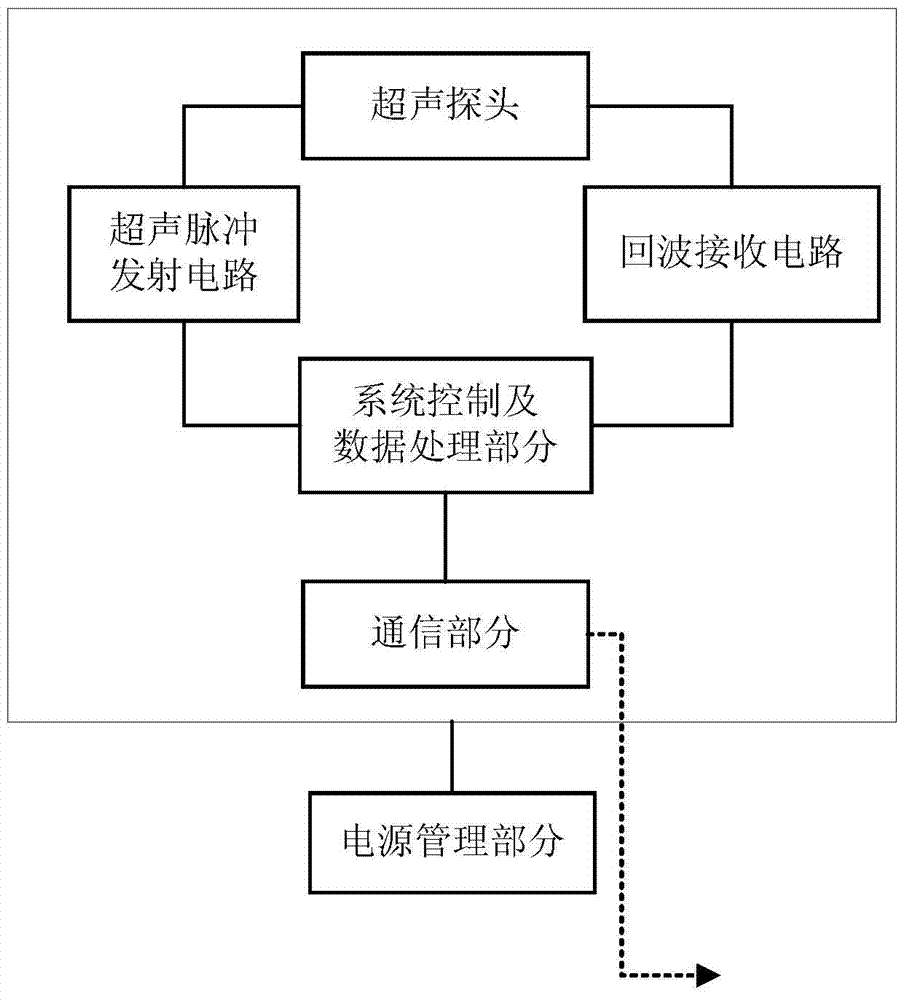
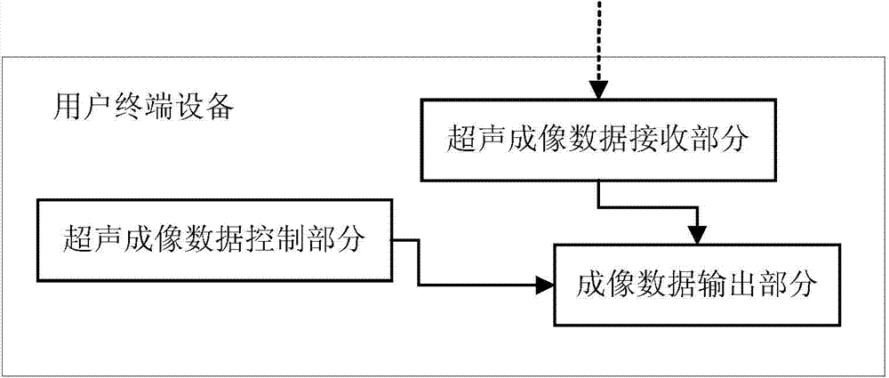
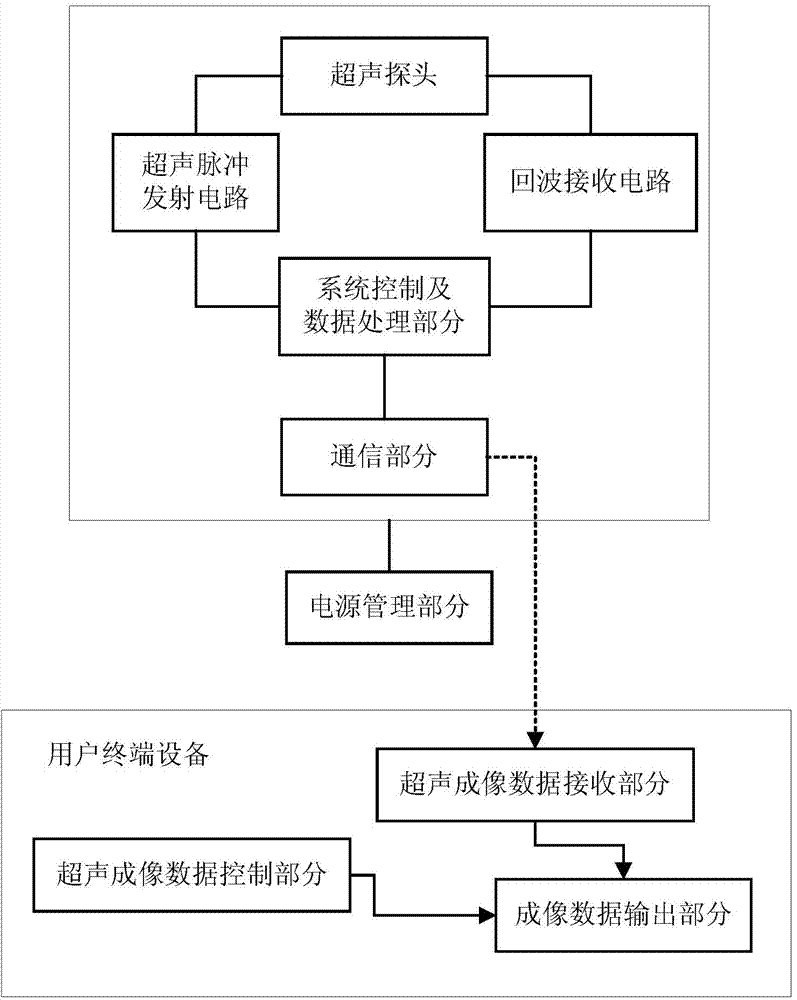
The invention discloses portable ultrasonic imaging equipment and a portable ultrasonic imaging system. The portable ultrasonic imaging equipment comprises an ultrasonic probe, a system control and data processing unit and a communication unit. The ultrasonic probe is used for converting electric signals into ultrasonic waves, emitting the ultrasonic waves, receiving ultrasonic echoes, converting the ultrasonic echoes into electric signals and sending the electric signals to the system control and data processing unit. The system control and data processing unit is used for controlling ultrasonic wave emission and ultrasonic echo reception and performing imaging processing on the electric signals acquired after conversion of the ultrasonic echoes according to an ultrasonic imaging algorithm to acquire imaging data. The communication unit is used for sending the imaging data acquired by the system control and data processing unit to receiving equipment. The receiving equipment is used for performing ultrasonic image displaying on the received imaging data and sending images via the internet. Mobile terminal equipment has a networking communication function of a split type ultrasonic imaging system, so that a user can upgrade and update the networking communication function via a client side conveniently and rapidly; the portable ultrasonic imaging equipment has the advantages of low cost, small size, low power consumption and the like.

Description

technical field [0001] The invention relates to the technical field of ultrasonic imaging, in particular to a portable ultrasonic imaging device and system. Background technique [0002] As a medical imaging technology, ultrasound imaging technology has been widely concerned and fully used in clinical diagnosis. At present, the ultrasonic imaging system widely used is mainly large floor-standing equipment, which is the size of a desktop computer, and needs a special cart to carry it. This ultrasonic imaging system cannot be flexibly applied to some diagnostic sites, such as for wounded and sick personnel at disaster relief sites. Diagnosis, diagnosis for the elderly with limited mobility at home, etc. [0003] To this end, the industry has provided a portable ultrasound imaging system, which is powered by batteries, can be carried around, and can obtain ultrasound images of patients' human tissues and organs anytime and anywhere, providing an important basis for doctors' on...

Claims


Application Information

Patent Timeline
Patent Type & Authority Applications(China)
IPC IPC(8): A61B8/00
CPCA61B8/4427A61B8/44A61B8/4444A61B8/52A61B8/565
Inventor 杜宏伟陆伟李力张义飞朱振涛陈思同
Owner UNIV OF SCI & TECH OF CHINA
Learn More