Spine screw

A screw and spine technology, applied in the field of bone anchor devices in spinal repair, can solve problems such as screw breakage, and achieve the effects of facilitating removal of broken screws, reducing bone damage, and facilitating revision

Active Publication Date: 2015-08-19
BEIJING NATON TECH GRP CO LTD +2
View PDF3 Cites 10 Cited by
  • Summary
  • Abstract
  • Description
  • Claims
  • Application Information

AI Technical Summary

Problems solved by technology

However, as the depth of the thread increases, the circumferential force of the screw increases at the same time. If the traditional one-piece rigid screw is used, it is likely to cause the screw to break. Therefore, it is also essential to ensure the micro-motion of the screw in the direction of the force.

Method used


Image

  • Spine screw
  • Spine screw
  • Spine screw

Examples


Embodiment Construction

[0024] The split-type spinal screw of the present invention will be further described in detail through specific embodiments below.

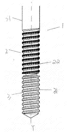
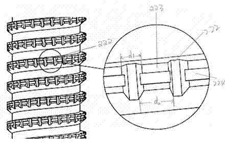
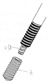
[0025] Such as Figure 1-3 As shown, the body 1 is the main body of a split-type pedicle screw, which defines the longitudinal axis Y, and the body is made of titanium alloy or PEEK material. The split-type screw includes an upper segment 2 and a lower segment 3 (integrated with cortical bone and cancellous bone respectively ), the upper section 2 includes a head portion 21, a rod portion 22, and a tail portion 23. The rod portion 22 has a first thread structure 221, and the first thread structure is provided with interval grooves 222 along the longitudinal direction. The grooved The shape can be trapezoidal groove, rectangular groove, or curved groove. Such as figure 2 As shown, the corresponding thread protrusion 223 is arranged adjacent to the groove, and the protrusion here is relative to the groove, that is, the distance between the toot...


PUM


Abstract

The invention provides a spine screw. The screw holding force and pulling resisting force are increased, the stable jointing of the screw in different bone regions is guaranteed effectively, and the fine effects are provided for promoting osseointegration promotion and guaranteeing long-term screw stability.

Description

technical field [0001] The invention relates to the field of orthopedic implants, and further relates to a bone anchor device in spinal repair. Background technique [0002] Common orthopedic diseases, such as lumbar disc herniation, spinal fractures, scoliosis, etc., often require surgical internal fixation, and spinal screw fixation is a common technique in orthopedic surgery. At present, most screws are fixed with a single thread on the main body of the screw rod. Due to the different bone quality of cortical bone and cancellous bone, the holding force of the screw in these two areas is also different. If a screw with a single thread form is used, it may Because of local stress concentration, the screw breaks. If the thread is too dense, the thread depth will be relatively small, otherwise the screw rigidity is not good, but the combination effect of too dense thread and cancellous bone is not good, which will cause the initial fixation instability. If the thread Too loo...

Claims


Application Information

Patent Timeline
Patent Type & Authority Applications(China)
IPC IPC(8): A61B17/86A61B17/70
CPCA61B17/7001A61B17/863A61B17/8685
Inventor 杨大诚刘云
Owner BEIJING NATON TECH GRP CO LTD
Why Eureka
Try Eureka