A Capsule Tank with Stable Transmission Capability

A technology of transmission capacity and storage tank, which is applied in the direction of transportation of passenger cars, transportation and packaging, tank cars, etc. It can solve the problems of affecting oil flow, box damage, impact, etc., and achieve the effect of reducing flow resistance and improving discharge efficiency

Active Publication Date: 2017-07-28
AEROSPACE RES INST OF MATERIAL & PROCESSING TECH +1
View PDF4 Cites 0 Cited by
  • Summary
  • Abstract
  • Description
  • Claims
  • Application Information

AI Technical Summary

Problems solved by technology

However, compared with pipeline transportation, due to the shape of the tank, this traditional oil flow is unstable during the start and stop of discharge and transportation.
Especially at the outlet of the storage tank, flow dead angle and turbulent flow are formed, which will cause pulsation, vibration and impact on the storage tank body, causing damage to the tank body or affecting the service life of the storage tank
At the same time, due to the long storage time of the oil in the storage tank, the low temperature and other factors promote the thickening of the oil in the storage tank, which affects the flow of the oil in the discharge process of the storage tank. Therefore, it is necessary to improve the discharge structure of the oil storage tank and improve the discharge efficiency.

Method used


Image

  • A Capsule Tank with Stable Transmission Capability
  • A Capsule Tank with Stable Transmission Capability
  • A Capsule Tank with Stable Transmission Capability

Examples


Embodiment 1

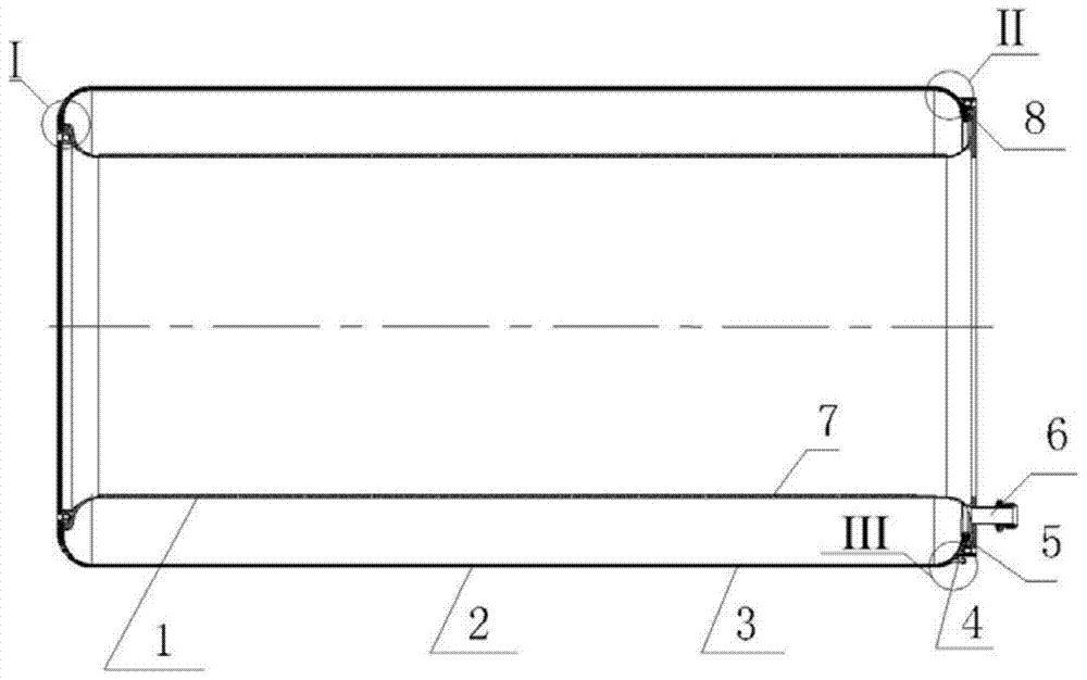
[0022] Such as figure 1 As shown, a capsule-type storage tank with stable transmission capacity includes a storage tank body, pipes and rubber capsules;

[0023] The bottom end of the pipe is fixedly connected with the bottom end of the tank body; through holes are evenly distributed on the side wall of the pipe;

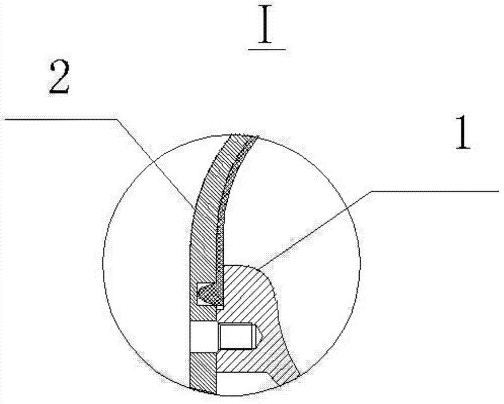
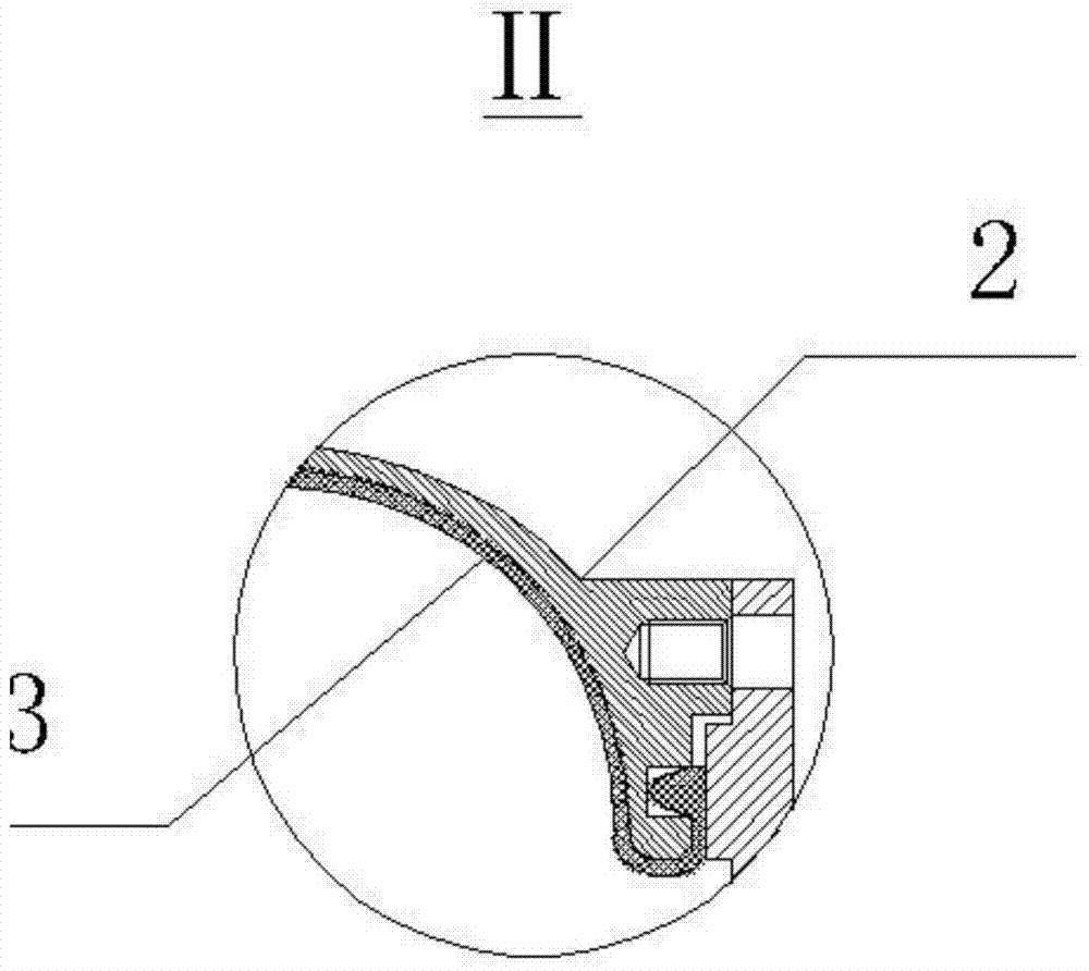
[0024] The rubber capsule is a flexible cylindrical structure with an upper opening and a lower opening, and the bottom and top of the rubber capsule have flanges;

[0025] The rubber capsule is set between the pipe and the tank body, the flange at the bottom of the rubber capsule is fixed in the sealing groove 8 at the bottom inside the tank body, and the flange at the top of the rubber capsule is fixed in the sealing groove 8 at the top of the tank body Inside, so that the fuel is sealed in the rubber capsule, so that the fuel is not filled between the rubber capsule and the tank body;

[0026] The tank body is provided with a gas nozzle, through which the inert...

Embodiment 2

[0039] The designed tank body 2 has a diameter of The total length is 1800mm, and the material is glass fiber / epoxy composite material. The wall thickness of the storage tank is 8mm. The outer wall of the storage tank is provided with an air nozzle 5 . The air nozzle and the box are sealed by epoxy bonding. The sealing groove 8 on the bottom end of the storage tank and the opening end face is 5mm (wide) * 4mm (deep). The sealing parts of the flanges of the corresponding rubber capsules 3 have a height of 6 mm, a width of 3 mm, and a rectangular shape. The material of the rubber capsule 3 is neoprene, the tensile strength is ≥13MPa, and the elongation at break is ≥180%. The rest of the rubber capsule 3 is designed and prepared according to the shape of the tank, and the thickness of the capsule 3 is 3mm. Plug the rectangular sealing parts at both ends of the capsule body 3 into the corresponding sealing grooves of the box respectively. The pipe body 1 is made of composit...


PUM


Abstract

The invention belongs to the field of design of fuel tanks and relates to a capsule tank with stable delivery performance, applicable to industries such as petroleum and aerospace. At the premise of not affecting the oil-storing capacity of the tank, the process of discharging the oil from the tank is changed into the process of flowing in a pipe. An oil discharge pipe is disposed within the tank by means of welding and the like and is provided with an oil outlet; the oil discharge pipe is included in a rubber capsule; the rubber capsule is attached to the inner wall of a tank body; fuel oil can be exchanged through the oil outlet and can be injected into the rubber capsule or discharged out of the same; the rubber capsule is flanged, thus having a seal structure, and the rubber capsule can be in flange connection with the end face of the tank body, ensuring end face tightness of the rubber capsule and the end face of the tank body; inertia gas is injected into a housing of the tank through a nozzle; with increase in the gas content, pressure increases gradually and compresses the rubber capsule which contracts and deforms in the middle; the fuel oil is exchanged through the oil outlet of the oil discharge pipe and is evenly discharged.

Description

technical field [0001] The present invention relates to an improved discharge structure of an oil storage tank. In particular, the structural design of a storage tank with a rubber capsule structure belongs to the field of fuel storage tank design and can be applied to petroleum, aviation, aerospace and other industries. Background technique [0002] The transportation and storage of fuel oil, kerosene and other oil materials play an important role in petroleum, aviation, aerospace and other fields. Usually, the oil discharge process mainly relies on pumps, pistons, gas pressurization, etc. to press the oil to generate a pressure difference in the storage tank to cause flow, discharge from the tank, and supply hydraulic components and engine components. However, compared with pipeline transportation, due to the shape of the tank body, this conventional method has unstable oil flow during the start and stop of discharge and transportation. Especially at the outlet of the st...

Claims


Application Information

Patent Timeline
Patent Type & Authority Patents(China)
IPC IPC(8): B65D88/54B65D88/74B65D90/00
CPCB65D88/54B65D88/745
Inventor 张继华皂伟涛冯华东刘小艳朱巍陈江涛
Owner AEROSPACE RES INST OF MATERIAL & PROCESSING TECH
Why Eureka
Try Eureka