Deeply-buried pool construction method for gridded underground continuous-wall foundation pit support

An underground diaphragm wall and foundation pit enclosure technology, applied in water conservancy engineering, infrastructure engineering, excavation, etc., can solve the problems of inability to meet the stability and safety of the pool structure, a large amount of construction waste, etc., to avoid construction waste and project progress. Fast and simple construction process

Inactive Publication Date: 2015-08-19
ZHONGCHUAN NO 9 DESIGN & RES INST
View PDF5 Cites 2 Cited by
  • Summary
  • Abstract
  • Description
  • Claims
  • Application Information

AI Technical Summary

Problems solved by technology

In the past ten years, the development of underground space in major cities in my country has developed rapidly, and a large number of technically complex foundation pit engineering construction projects have emerged. Many new technologies have emerged in various aspects such as foundation pit design theory, construction methods, and construction management techniques, such as In the foundation pit enclosure project of the reverse method, the temporary enclosure structure of the foundation pit is combined with the main structure of the basement, which simplifies the construction process, but the later demolition of the temporary structure of the foundation pit causes a large amount of construction waste
However, the deep-buried pool is different from the conventional basement structure. The pool is a "U"-shaped open structure without internal support components, so that the combination of the enclosure structure and the main structure of the basement in the prior art cannot meet the stability and safety of the pool structure itself. requirements

Method used


Image

  • Deeply-buried pool construction method for gridded underground continuous-wall foundation pit support
  • Deeply-buried pool construction method for gridded underground continuous-wall foundation pit support
  • Deeply-buried pool construction method for gridded underground continuous-wall foundation pit support

Examples


Embodiment 1

[0015] The present invention will be further described below with certain engineering pond, and this pond length is 68m, width 28m, and excavation depth is 21m.

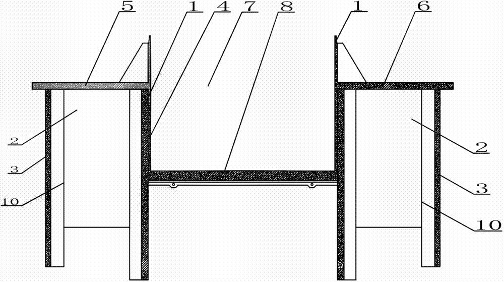
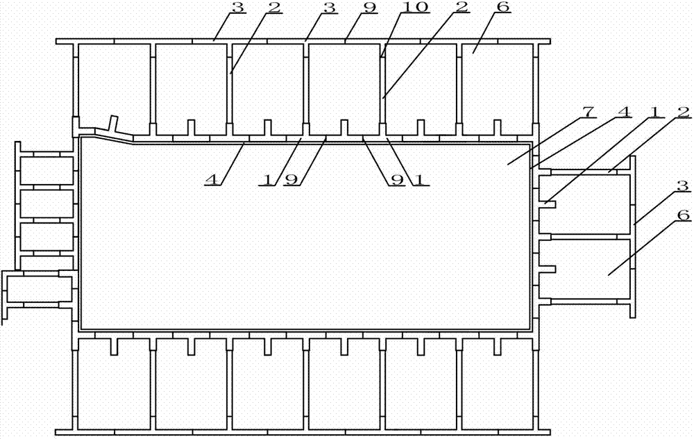
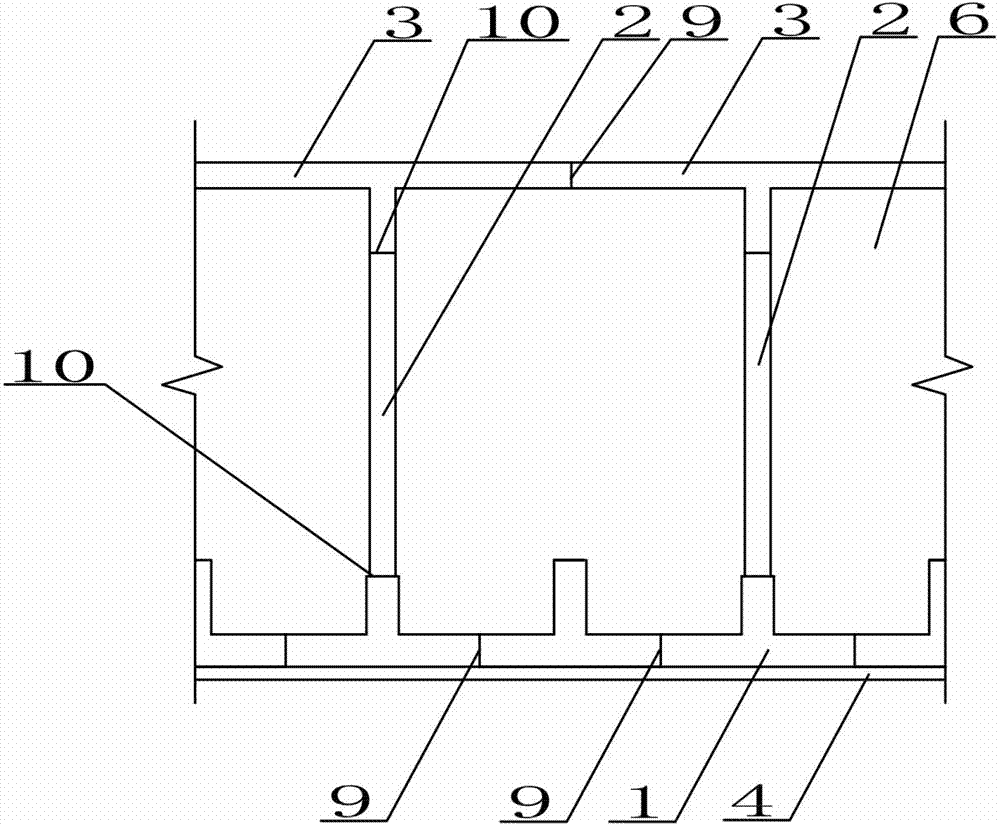
[0016] See attached figure 1 ~ attached figure 2 , the present invention consists of a grid-shaped underground continuous wall 6 and a deep buried pool 7, the grid-shaped underground continuous wall 6 is a front wall 1 and a rear wall 3 and a web 2 arranged between the front wall 1 and the rear wall 3, The top plate 5 is connected as a grid-shaped ground wall of the overall structure; the deep-buried pool 7 is a "U"-shaped open pool formed by the pool side wall 4 and the pool bottom plate 8, and the deep-buried pool 7 is formed by a lattice-shaped underground continuous wall 6 In order to resist the lateral force retaining structure, the vertical earthwork excavation without internal support structure is carried out in the foundation pit enclosure formed by the lattice underground diaphragm wall 6, and its specific...


PUM


Abstract

The invention discloses a deeply-buried pool construction method for a gridded underground continuous-wall foundation pit support. The method includes construction of a gridded underground continuous wall and a deeply-buried pool structure, and is characterized in that a deeply-buried pool takes the gridded underground continuous wall as a lateral force resistant soil retaining structure, and vertical earth excavation of an inner-support free structure is performed in the foundation pit support formed by the gridded underground continuous wall. The construction method specially includes the steps of building of the underground continuous wall and construction of the main pool structure. Compared with the prior art, the deeply-buried pool construction method has the advantages that the construction process is simple, progress of the construction is fast, construction waste caused by subsequent dismantling of a temporary foundation pit structure is avoided, energy conservation and emission reduction are achieved, the process is green and environment friendly, and the method is especially suitable for construction of pool structures with soft layers deeply buried by less than 15 meters.

Description

technical field [0001] The invention relates to the technical field of deep foundation pit enclosure, in particular to a method for constructing a deep buried water pool for a grid-shaped underground diaphragm wall foundation pit enclosure used for deep water tests of deep foundation pit enclosure. Background technique [0002] The 21st century is the marine century. As my country's investment in marine engineering and ship engineering design continues to increase, the demand for deep water test tanks is also increasing. As the test content and complexity continue to increase, the requirements for the depth, scale and functionality of the test pool are also getting higher and higher. There are more and more deep-buried pool structures, and some of them are even buried deeper than 30m. [0003] At present, the deep-buried pool structure requires the construction of the foundation pit enclosure first, and then the pool structure. The two are independent of each other, which no...

Claims


Application Information

Patent Timeline
Patent Type & Authority Applications(China)
IPC IPC(8): E02D29/045E02D17/04E02D29/02
Inventor 李华梅田巴元吴昊喻斌文符晓贇金国龙徐剑林靖田振
Owner ZHONGCHUAN NO 9 DESIGN & RES INST
Why Eureka
Try Eureka