Control valve for thermal management module

A technology for controlling valves and valve housings, applied in coolant flow control, sliding valves, valve devices, etc., can solve the problem of Teflon losing shape stability, shorten installation time, reduce costs, and compensate for losses Effect

Inactive Publication Date: 2015-08-19
SCHAEFFLER TECH AG & CO KG
View PDF6 Cites 5 Cited by
  • Summary
  • Abstract
  • Description
  • Claims
  • Application Information

AI Technical Summary

Problems solved by technology

PTFE (trade name Teflon) is known for its good friction properti

Method used


Image

  • Control valve for thermal management module

Examples


Embodiment Construction

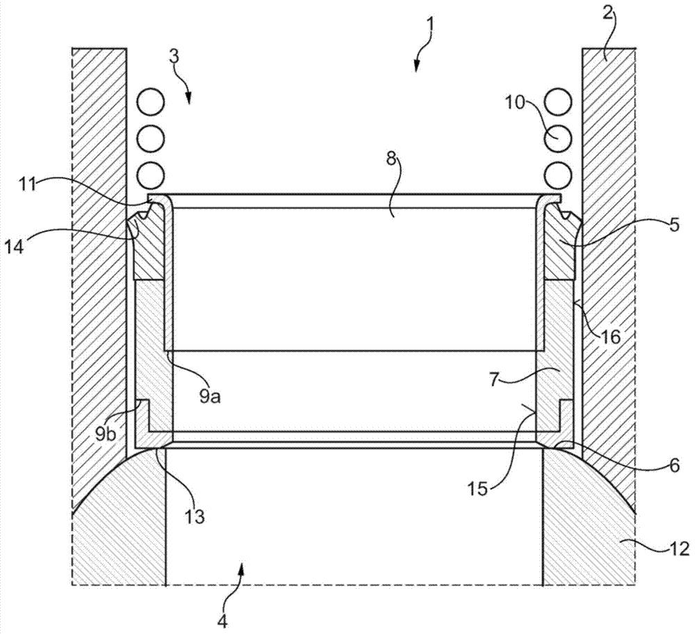
[0012] figure 1 The control valve 1 is shown in cross section. The control valve 1 has a valve housing 2 on which is provided an inlet connection 3 for cooling water which, depending on the position of a valve element 12 installed in the valve housing 2 , can be connected to an outlet connection 4 . In order to adequately seal the coolant flow path, the control valve 1 has a sealing ring 5 which seals in the radial direction and a sealing element 6 which seals in the axial direction.

[0013] The sealing element 6 bears against the outer circumferential surface of the valve element 12 by means of its end face formed as a sealing surface 13 which is adapted to the outer contour of the valve element 12 . In this way a minimum sealing gap is obtained. This sealing gap is further reduced by the fact that the pressure of the spring 10 acts indirectly on the sealing element 6 in the axial direction. The spring 10 ensures the pressing pressure required to ensure a sufficient seal ...


PUM


Abstract

The invention relates to a control valve for regulating a coolant circuit of an internal combustion engine, preferably, controlling different cooling water flowing in a thermal management module. The control valve has a valve housing, on which a supply port for cooling water is arranged, which is connectable to an exhaust port, depending on the position of the valve body housed in the valve housing. Thus, the coolant flow paths are adequately sealed, the control valve comprises a sealing ring, which seals in the radial direction, and a sealing element which seals in an axial direction.

Description

technical field [0001] The invention relates to a control valve for controlling a cooling medium circuit of an internal combustion engine, preferably for controlling different cooling water flows in a thermal management module. The control valve has a valve housing on which an inlet connection for cooling water is arranged, which inlet connection can be connected to an outlet connection depending on the position of a valve element installed in the valve housing. In order to adequately seal the coolant flow path, the control valve has a sealing ring which seals in the radial direction and a sealing element which seals in the axial direction. Background technique [0002] A control valve of the type described above is known from document DE 10 2009 014 047 A1. The aforementioned document relates to a control valve for controlling the circulation of a cooling medium in an internal combustion engine, said control valve having a first inlet connection for bypass-circulated cooli...

Claims


Application Information

Patent Timeline
IPC IPC(8): F16J15/00F16K51/00F01P7/16
CPCF16K5/0464F16J15/3252F16J15/56F16K3/243F16K3/262F16K51/00F01P7/16
Inventor 迈克尔·韦斯马库斯·京茨尔乌利·格罗斯科普夫
Owner SCHAEFFLER TECH AG & CO KG
Why Eureka
Try Eureka