An air cooling device for high heat light source

An air-cooling device and air-cooling technology, applied in lighting devices, components of lighting devices, cooling/heating devices of lighting devices, etc., can solve problems such as lowering system performance, increasing system risk, and difficulty in completely eliminating vibration, and achieving Improve system performance, reduce system risk, save procurement and maintenance costs

Active Publication Date: 2017-01-11
RAINTREE SCI INSTR SHANGHAI
View PDF5 Cites 0 Cited by
  • Summary
  • Abstract
  • Description
  • Claims
  • Application Information

AI Technical Summary

Problems solved by technology

[0003] The usual liquid cooling system is prone to clogging and leakage due to reasons such as sealing and aging, and the reliability is poor
[0004] However, fans are used to cool high-temperature heat sources. The fan power and size are relatively large, and vibration is difficult to completely eliminate, which will inevitably reduce system performance (for example, signal-to-noise ratio) and may increase system risks.

Method used


Image

  • An air cooling device for high heat light source
  • An air cooling device for high heat light source
  • An air cooling device for high heat light source

Examples


Embodiment Construction

[0027] In the following detailed description of the preferred embodiment, reference is made to the accompanying drawings which form a part hereof. The accompanying drawings show, by way of example, specific embodiments in which the invention can be practiced. The illustrated embodiments are not intended to be exhaustive of all embodiments in accordance with the invention. It is to be understood that other embodiments may be utilized and structural or logical changes may be made without departing from the scope of the present invention.

[0028] In the following specific descriptions, directional terms such as "left", "right", "top", "bottom", "front", "rear", "lead", "forward", "rear" etc. , used with reference to the directions described in the attached drawings. Components of embodiments of the present invention may be positioned in a variety of different orientations, and directional terms are used for purposes of illustration and not limitation.

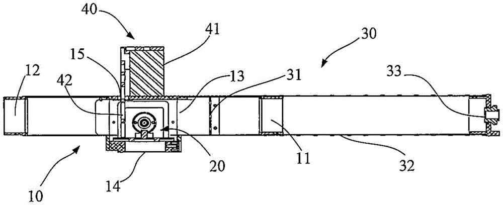
[0029] figure 1 A cro...


PUM


Abstract

The invention provides an air cooling device for a high-heat light source. The air cooling device comprises an air cooling cavity component, a lamp housing component and an air guide shunt component. The air cooling cavity component comprises an air inlet cavity, an air outlet cavity and an air cooling cavity for connecting the air inlet cavity with the air outlet cavity; and a light outlet window is formed in the bottom of the air cooling cavity. The lamp housing component is positioned in the air cooling cavity of the air cooling cavity component, and is provided with a lamp housing shell. The air guide shunt component comprises a current limiting plate, an air guide pipe and an air diffusion sleeve. Compressed cooling air from a factory compressed air system enters the air cooling cavity from the air inlet cavity through the air diffusion sleeve and the air guide pipe, takes away the heat generated by an adjustable light source from the periphery of the lamp housing component through the current limiting plate, and is discharged from the air outlet cavity. The air cooling device uses the clean compressed air provided by the factory compressed air system, so that the purchase and maintenance cost of a cooling fan is saved, and the system risk is reduced.

Description

technical field [0001] The invention relates to an air-cooling device for a high-calorie light source, which is suitable for various precision measurement or precision processing equipment, especially for semiconductor large-scale integrated circuit manufacturing and measurement equipment. Background technique [0002] The light source in optical equipment often has a high calorific value, and the precision measurement system itself is relatively sensitive to temperature changes, so it has high requirements for the thermal stability of the environment inside the equipment, so the heat should be discharged from the system, and it must be ensured The reliability of the system; on the other hand, as part of the measurement system, the light source often needs to be precisely adjusted and positioned relative to other parts of the optical path, and minimize vibration and shock. [0003] The usual liquid cooling system is prone to clogging and leakage due to reasons such as sealin...

Claims


Application Information

Patent Timeline
Patent Type & Authority Patents(China)
IPC IPC(8): F21V3/02F21V29/50
CPCF21V3/00
Inventor 马涛高海军刘军凯
Owner RAINTREE SCI INSTR SHANGHAI
Why Eureka
Try Eureka