Piezoelectric ceramic inductor and integrated inductor comprising piezoelectric ceramic inductor

A technology of piezoelectric ceramics and piezoelectric ceramic sheets, applied in the field of piezoelectric devices, can solve the problems of complex manufacturing process, inconvenient integration, and large volume, and achieve the effects of easy integration, no electromagnetic interference, and small volume

Inactive Publication Date: 2015-08-19
SUZHOU INST OF BIOMEDICAL ENG & TECH CHINESE ACADEMY OF SCI
View PDF2 Cites 10 Cited by
  • Summary
  • Abstract
  • Description
  • Claims
  • Application Information

AI Technical Summary

Problems solved by technology

[0003] Therefore, the technical problem to be solved by the present invention is to overcome the disadvantages of large volume, complex manufacturing process and inconvenient integration in the prior art of electromagnetic inductors, and propose a piezoelectric ceramic inductor with small volume and easy integration and including the Integrated inductors of piezoelectric ceramic inductors, which also have the advantages of low cost and easy production

Method used


Image

  • Piezoelectric ceramic inductor and integrated inductor comprising piezoelectric ceramic inductor
  • Piezoelectric ceramic inductor and integrated inductor comprising piezoelectric ceramic inductor
  • Piezoelectric ceramic inductor and integrated inductor comprising piezoelectric ceramic inductor

Examples


Embodiment 1

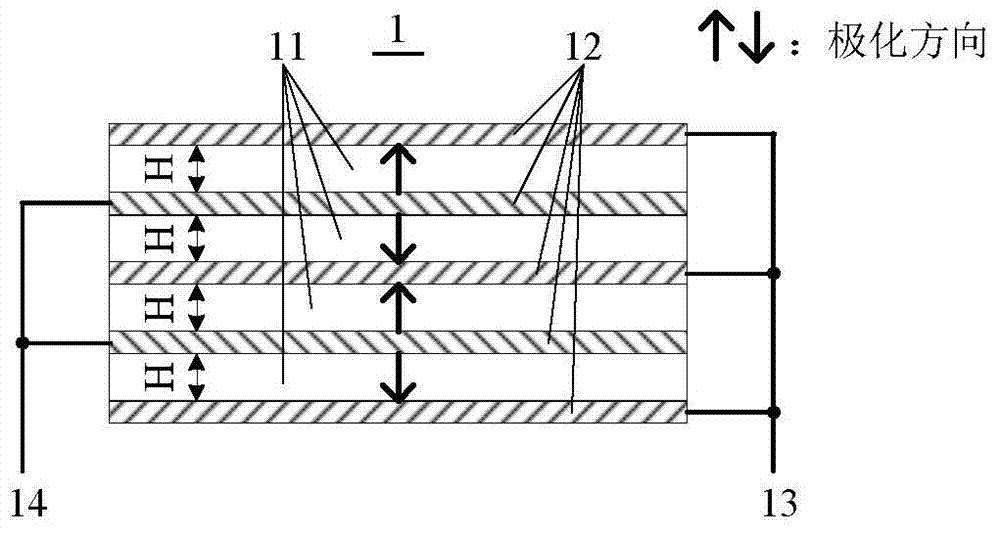
[0039] figure 1 A schematic side view showing the piezoelectric ceramic inductor of Embodiment 1, as figure 1 As shown, a piezoelectric ceramic inductor 1 of this embodiment includes four piezoelectric ceramic sheets 11 stacked with the same thickness, all of which have a thickness of H, and the thicknesses may also be different or partly the same when designed according to actual needs; The polarization directions of the two adjacent piezoelectric ceramic sheets 11 are opposite.

[0040] Electrode layers 12 are provided on the upper end surface of the topmost piezoelectric ceramic sheet 11, on the lower end surface of the bottommost piezoelectric ceramic sheet 11, and between two adjacent piezoelectric ceramic sheets 11. On each of the electrode layers 12 All have electrode leads.

[0041] The electrode lead-out lines on the odd-numbered electrode layers 12 are connected, that is, the electrode lead-out lines on the first, third, and fifth-layer electrode layers 12 are conn...

Embodiment 2

[0049] Figure 4 A schematic side view showing the piezoelectric ceramic inductor of Embodiment 2, as Figure 4 As shown, a piezoelectric ceramic inductor 2 in this embodiment includes four stacked piezoelectric ceramic sheets 21 with the same thickness, the thickness of which is H, and the thickness can also be different or partly the same when designing according to actual needs; The polarization direction of each piezoelectric ceramic sheet 21 is the same.

[0050] An upper electrode layer 22 is arranged on the upper end surface of each piezoelectric ceramic sheet 21, and a lower electrode layer 25 is arranged on the lower end surface; electrodes are arranged on each upper electrode layer 22 and the lower electrode layer 25. Lead wires; an insulating layer 26 is provided between the adjacent lower electrode layer 25 and upper electrode layer 22 .

[0051] The electrode lead-out lines on each upper electrode layer 22 are connected to form the first electrode lead-out line ...

Embodiment 3

[0055] Figure 5 shows a schematic structural view of the piezoelectric ceramic inductor of embodiment 3, as Figure 5 As shown, a piezoelectric ceramic inductor 3 in this embodiment includes two stacked piezoelectric ceramic sheets 31 with the same thickness, both of which have a thickness of H, and the thicknesses may also be different or partly the same when designed according to actual needs; The polarization directions of the two adjacent piezoelectric ceramic sheets 31 are opposite.

[0056] An electrode layer 32 is provided on the upper end surface of the first piezoelectric ceramic sheet 31, on the lower end surface of the second piezoelectric ceramic sheet 31, and between the two piezoelectric ceramic sheets 31, and each electrode layer 32 has a Equipped with electrode leads.

[0057] The electrode lead-out lines on the odd-numbered electrode layers 32 are connected, that is, the electrode lead-out lines on the first and third electrode layers 32 are connected to fo...


PUM


Abstract

The invention discloses a piezoelectric ceramic inductor and an integrated inductor comprising the piezoelectric ceramic inductor. The piezoelectric ceramic inductor comprises at least two piezoelectric ceramic plates arranged in a laminating mode; the adjacent two piezoelectric ceramic plates have opposite polarization directions; electrode layers are arranged on the upper end surface of the top piezoelectric ceramic plate, the lower end surface of the bottom piezoelectric ceramic plate and between the adjacent two piezoelectric ceramic plates; each electrode layer is provided with an electrode leading-out wire; electrode leading-out wires on the electrode layers of odd numbers are connected to form a first electrode leading-out wire of the piezoelectric ceramic inductor; electrode leading-out wires on the electrode layers of even numbers are connected to form a second electrode leading-out wire of the piezoelectric ceramic inductor. The piezoelectric ceramic inductor has a structure of multiple layers of piezoelectric ceramic plates, and has the advantages of small volume, low cost and easy integration.

Description

technical field [0001] The invention relates to the technical field of piezoelectric devices, in particular to a piezoelectric ceramic inductor and an integrated inductor including the piezoelectric ceramic inductor. Background technique [0002] An inductor is a circuit component specially used to realize inductance in a circuit, which can convert electrical energy into magnetic energy and store it. Most of the existing inductors are electromagnetic inductors, which are made of a conductive material coiled around a magnetic core, typically copper wire, and the magnetic core can also be removed or replaced by a ferromagnetic material. There are many kinds of inductors with different shapes. Air-core inductors include: single-layer flat-wound air-core inductor coils, multi-layer air-core inductor coils, inter-wound air-core inductor coils, bodiless air-core coils, etc.; other forms of inductors include: : Honeycomb inductor coil, inductor coil with magnetic core, magnetic ta...

Claims


Application Information

Patent Timeline
Patent Type & Authority Applications(China)
IPC IPC(8): H01L41/083H01F37/00
Inventor 邵维维徐杰崔崤峣
Owner SUZHOU INST OF BIOMEDICAL ENG & TECH CHINESE ACADEMY OF SCI
Why Eureka
Try Eureka