High-strength stator iron core

A stator core, high-strength technology, applied in the magnetic circuit shape/style/structure, electrical components, electromechanical devices, etc., can solve the problem of the limited diameter and strength of the cylindrical winding column, and the broken copper wire cylindrical winding column. , the connection is not tight enough, etc., to achieve the effect of improving stability and safety, long service life, and enhancing strength

Active Publication Date: 2015-08-19
HUZHOU YONGCHANG BEISHITUO ELECTRIC APPLIANCE INDAL
View PDF8 Cites 2 Cited by
  • Summary
  • Abstract
  • Description
  • Claims
  • Application Information

AI Technical Summary

Problems solved by technology

[0002] The winding posts on the core molded frame on the existing stator core are used to transition the wires from one iron core tooth to another iron core tooth in an orderly and safe manner. The copper wire has a large restraint force when running the wire, and the diameter and strength of the cylindrical winding post are limited. The pressure that cannot support the copper wire often causes the cylindrical winding post to break
At the same time, the terminal posts on the iron core plastic frame are connected to one side of the plastic frame, and the bottom is suspended, which is easy to deform and break during use.
The connection between the plastic frame and the inner surface of the iron core is not tight enough, and it is easy to disengage

Method used


Image

  • High-strength stator iron core
  • High-strength stator iron core
  • High-strength stator iron core

Examples


Embodiment 1

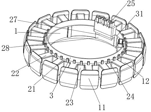
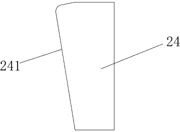
[0034] A high-strength stator core, comprising an iron core main body and an iron core plastic packaging frame wrapped on the iron core main body, the iron core main body includes an iron core inner ring 1 and iron cores arranged on the outer side of the iron core inner ring and alternately arranged Teeth 11 and tooth grooves 12. The iron core plastic package frame includes an inner ring part arranged on the inner ring of the iron core and a tooth wrapping part 22 wrapped on the iron core teeth. The end is exposed, and the inner ring part includes a top cover ring 21 covering the top of the inner ring of the iron core, a bottom cover ring 26 covering the bottom of the inner ring of the iron core, and a side covering the outer side of the inner ring of the iron core and corresponding to the position of the tooth groove. Cover surface 23, the outer side of the top cover ring is evenly distributed with square winding posts 24, and the inner side is provided with terminal posts 25,...

Embodiment 2

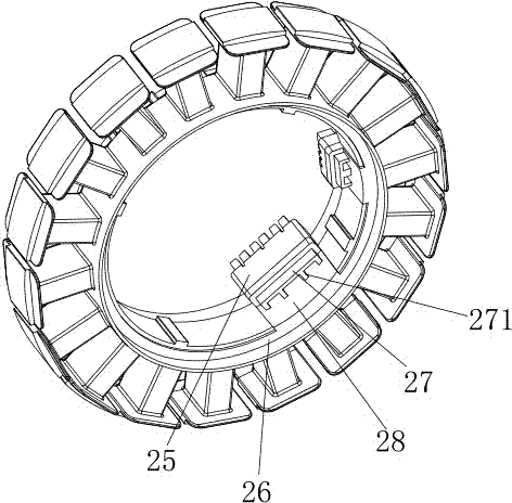
[0040] The difference from the above-mentioned embodiment is that the support and reinforcement part includes a reinforced support transition step 27 that extends downward from the bottom of the terminal and leans against the inner surface of the inner ring of the iron core.

Embodiment 3

[0042] The difference from the above-mentioned embodiments is that the support reinforcement part includes a support panel 28 extending from the bottom of the terminal post along the inner surface of the inner ring of the iron core to the bottom cover ring.


PUM


Abstract

The invention, which belongs to the motor field, particularly relates to a high-strength stator iron core comprising a main iron core body and an iron core plastic package rack coating the main iron core body. The main iron core body contains an iron core inner ring, iron core teeth, and gullets, wherein the iron core teeth and gullets are arranged at the outer side of the iron core inner ring and are arranged alternately. The iron core plastic package rack includes an inner ring part arranged on the iron core inner ring and tooth coating parts coating the iron core teeth; the inner side of the iron core inner ring and the outer ends of the iron core teeth are exposed; the inner ring part includes a top cover ring covering the top of the iron core inner ring, a bottom cover ring covering the bottom of the iron core inner ring, and side cover surfaces covering the outer side surface of the iron core inner ring and corresponding to the positions of the gullets; square winding posts are distributed at the outer side of the top cover ring and a binding post is arranged at the inner side of the top cover ring; and a support enhancement part is arranged at the bottom of the binding post. According to the application, because the high-strength square winding posts are arranged at the plastic package rack and the binding post sleeves the iron core inner ring by a support panel, strengths of all components of the plastic package rack is enhances, thereby improving stability of the motor using the stator iron core and prolonging the service life.

Description

technical field [0001] The invention belongs to the field of motors, and in particular relates to a high-strength stator core. Background technique [0002] The winding posts on the core molded frame on the existing stator core are used to transition the wires from one iron core tooth to another iron core tooth in an orderly and safe manner. The copper wire has a large restraint force when the wire is drawn, and the diameter and strength of the cylindrical winding post are limited. The pressure that cannot support the copper wire often leads to the breaking of the cylindrical winding post. At the same time, the terminal posts on the iron core plastic frame are connected to one side of the plastic frame, and the bottom is suspended, which is easy to be deformed and broken during use. The connection between the plastic frame and the inner surface of the iron core is not tight enough, and it is easy to disengage. Contents of the invention [0003] The object of the present ...

Claims


Application Information

Patent Timeline
Patent Type & Authority Applications(China)
IPC IPC(8): H02K1/14
CPCH02K1/145
Inventor 江林飞孙永庆孙豪远汪旭亮沈智威
Owner HUZHOU YONGCHANG BEISHITUO ELECTRIC APPLIANCE INDAL
Why Eureka
Try Eureka