
Manufacturing method of polarizing film

A manufacturing method and technology of polarizing film, which are applied in polarizing elements, chemical instruments and methods, instruments, etc., can solve the problems of weak mechanical strength and decreased polarization function, and achieve the effect of good fit and efficient manufacturing.

Active Publication Date: 2018-11-30
NITTO DENKO CORP
View PDF24 Cites 0 Cited by
  • Summary
  • Abstract
  • Description
  • Claims
  • Application Information

AI Technical Summary

Problems solved by technology

For such polarizers, the mechanical strength is extremely weak, and the polarizing function is significantly reduced due to shrinkage due to heat and moisture.

Method used


Image

  • Manufacturing method of polarizing film
  • Manufacturing method of polarizing film

Examples


Embodiment 1

[0152] (Process 1)

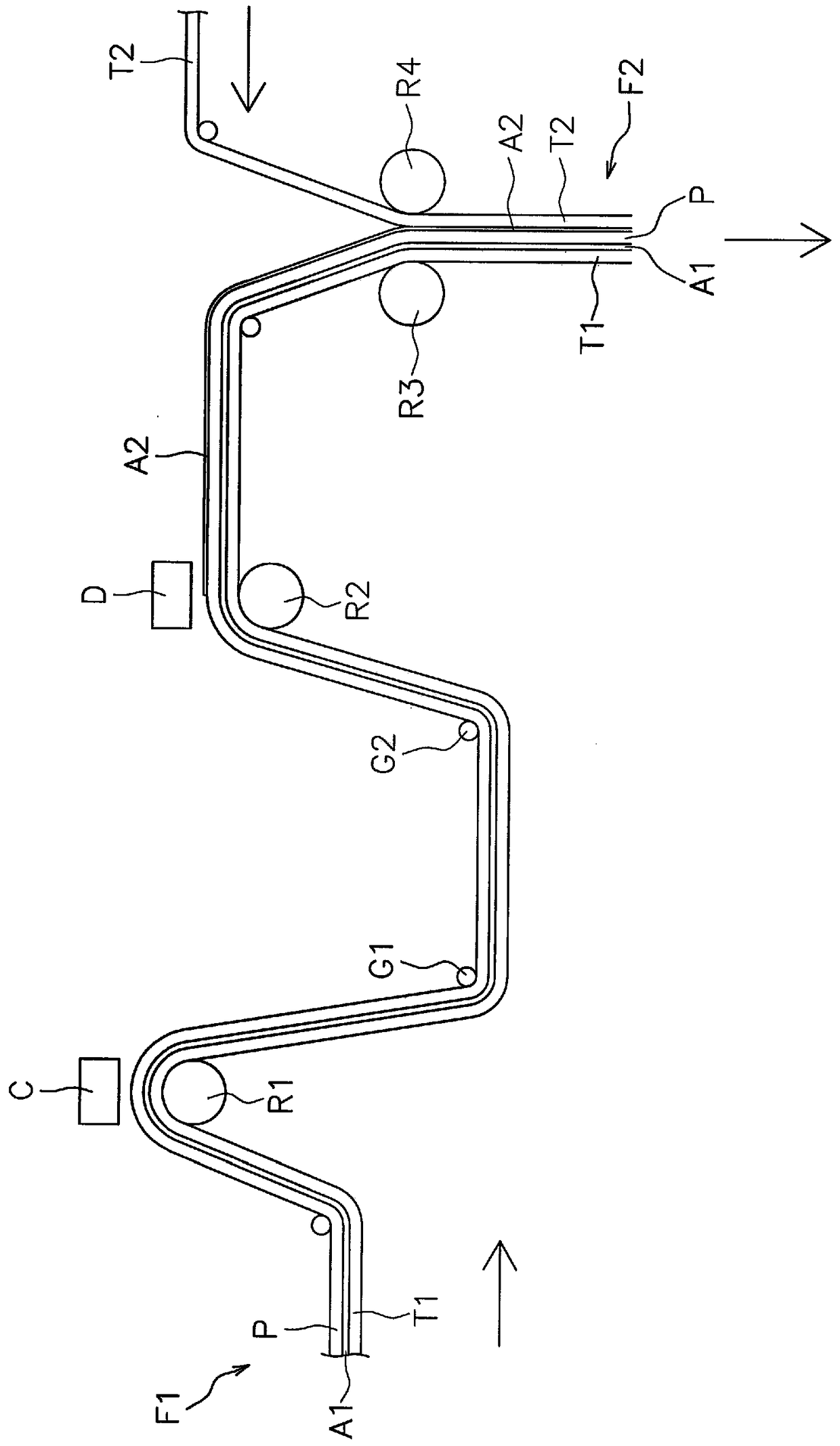
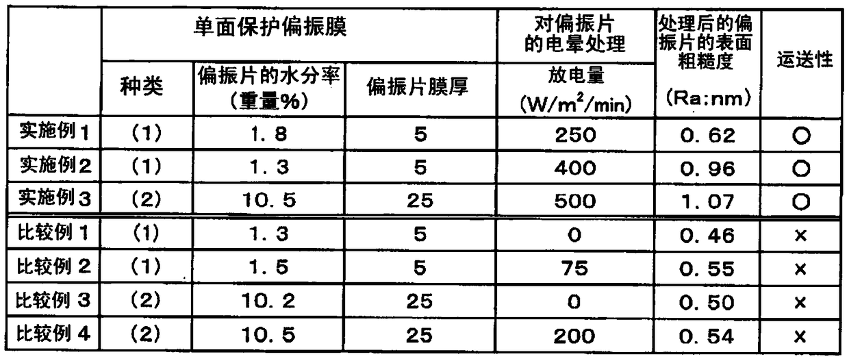
[0153] In such a way that the transparent protective film side of the sheet protective polarizing film (1) is the processing roll side, follow figure 1 The way, the transport sheet protects the polarizing film (1). Regarding the activation treatment, a corona irradiation machine (manufactured by Kasuga Denki Co., Ltd., CT-0212) was used with a discharge capacity of 250W / m 2 The condition of / min corona treatment is performed on one side of the polarizer. The surface roughness (Ra) of the surface of the polarizing plate after the activation treatment was 0.62 nm.

[0154] (Process 2)

[0155] Then, protect the polarizing film (1) with the surface of the polarizing plate activated, so that the polarizing plate side is the guide roller side, according to figure 1 The way, the transport sheet protects the polarizing film (1).

[0156] (Process 3)

[0157] Then, using a microgravure coater, the above-mentioned adhesive (active energy ray curable adhesive) was applied...

Embodiment 2~3、 comparative example 1~4

[0161] The polarizing film was produced in the same manner as in Example 1, except that the type of the sheet protective polarizing film and the corona discharge treatment amount on the polarizing plate in Example 1 were changed as shown in Table 1. In addition, the moisture content of the sheet protective polarizing film is controlled by the drying temperature.


PUM

PropertyMeasurementUnit
surface roughnessaaaaaaaaaa
thicknessaaaaaaaaaa
surface roughnessaaaaaaaaaa

Abstract

This polarizing film production method is characterized by having: (1) a step in which an activation process is conducted on a polarizer having a moisture content of not more than 11 wt% so as to provide a surface roughness (Ra) of 0.6 nm or higher; (2) a step in which the polarizer is conveyed while the surface of the activated polarizer is in contact with a guide roll; (3) a step in which an adhesive is applied to the polarizer and / or a transparent protective film; and (4) a step in which the polarizer and the transparent protective film are bonded together via the adhesive. This production method enables a polarizing film to be produced with good conveying properties.

Description

Technical field [0001] The present invention relates to a method of manufacturing a polarizing film. The polarizing film obtained by this manufacturing method can be formed into image display devices such as liquid crystal display devices (LCD), organic EL display devices, CRTs, PDPs, alone or in the form of optical films formed by stacking them. Background technique [0002] The market demand for liquid crystal display devices in the fields of watches, mobile phones, PDAs, notebook computers, personal computer monitors, DVD players, and televisions is rapidly increasing. The liquid crystal display device is a device that visualizes the polarization state caused by the conversion of liquid crystal, and uses a polarizing plate according to its display principle. Especially in TV and other applications, high brightness, high contrast, and wide viewing angle are increasingly required, and polarizing films are also beginning to require high transmittance, high degree of polarization...

Claims


Application Information

Patent Timeline
Patent Type & Authority Patents(China)
IPC IPC(8): G02B5/30G02F1/1335
CPCG02B5/3033B32B37/1284B32B37/203B32B38/0008B32B2038/0028B32B2038/166B32B2309/02B32B2309/105B32B2309/14B32B2457/202G02F1/133528G02F2201/50
Inventor 姜太艳齐藤武士品川雅冈本美纪
Owner NITTO DENKO CORP
Learn More