Supercharge Your Innovation With Domain-Expert AI Agents!

Electric device, and apparatus and method for bonding separator of electric device

A technology for an electrical device and a bonding device, which is applied in the manufacture of electrical components, non-aqueous electrolyte batteries, and electrolyte batteries, etc., can solve the problems of lowering electrical properties, scattering of heat-resistant materials of diaphragms, and thickening of diaphragm layers.

Inactive Publication Date: 2015-08-19
ENVISION AESC JAPAN LTD
View PDF9 Cites 3 Cited by
  • Summary
  • Abstract
  • Description
  • Claims
  • Application Information

AI Technical Summary

Problems solved by technology

[0011] In such a state, when the laminated battery vibrates or receives an impact, the heat-resistant material of the separator may be scattered and the electrical characteristics may be lowered.
In addition, the above-mentioned patent document 1 image 3 The separator shown has a heat-fused layer on both surfaces of the heat-resistant layer. Therefore, although the heat-resistant material does not scatter, the layer thickness of the separator becomes thicker.
[0012] Furthermore, none of the above-mentioned Patent Document 2 and Patent Document 3 is a structure that takes into consideration that the heat-resistant material that is easily scattered does not scatter when the separator formed by laminating the heat-resistant material and the molten material is transported.
[0013] In such a structure, in the case of using a diaphragm formed by laminating a heat-resistant material and a molten material, the heat-resistant material of the diaphragm may scatter in the diaphragm joining device.

Method used


Image

  • Electric device, and apparatus and method for bonding separator of electric device
  • Electric device, and apparatus and method for bonding separator of electric device
  • Electric device, and apparatus and method for bonding separator of electric device

Examples


no. 1 Embodiment approach

[0035] First, refer to Figure 1 ~ Figure 4 The structure of the electrical device 1 in which the diaphragms 30 are joined to each other using the diaphragm joining apparatus 100 of the first embodiment will be described.

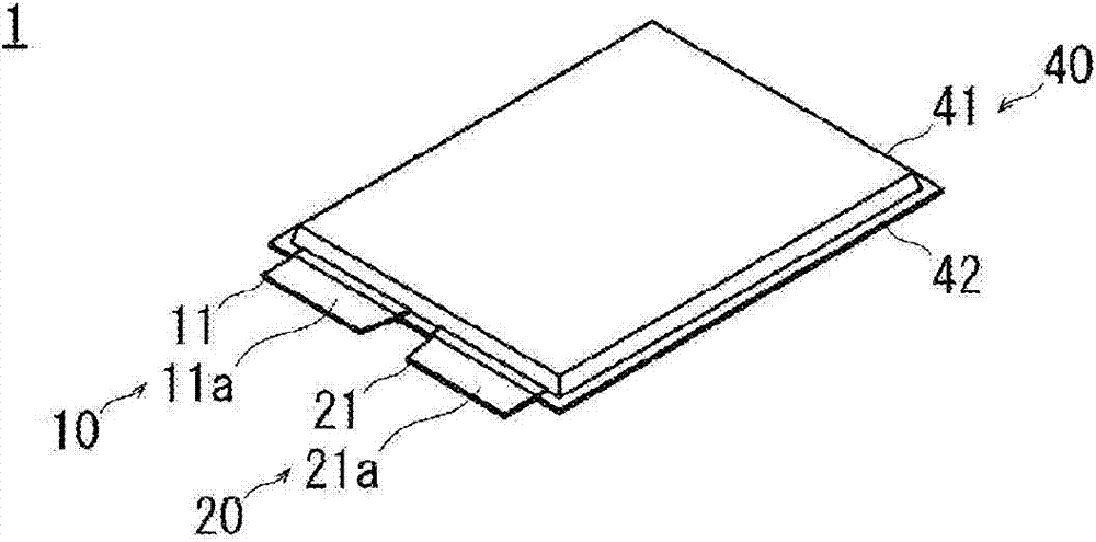
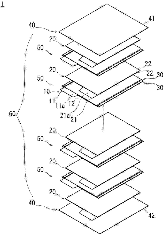
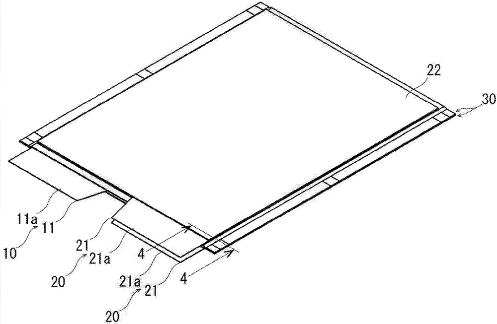
[0036] figure 1 It is a perspective view showing the electrical device 1 to which the diaphragm 30 is joined by the diaphragm joining apparatus 100 . figure 2 It is an exploded perspective view showing the electrical device 1 to which the diaphragm 30 is joined by the diaphragm joining apparatus 100 . image 3 It is a perspective view showing a state in which the negative electrode 20 is stacked on both ends of the packaged electrode 50 formed by packaging the positive electrode 10 with a pair of separators 30 using the separator bonding apparatus 100 . Figure 4 Yes image 3 Sectional view at line 4-4 shown.

[0037] like figure 1 As shown, the electric device 1 corresponds to, for example, a lithium-ion secondary battery, a polymer lithium battery...

no. 2 Embodiment approach

[0085] refer to Figure 11 The electrical device of the second embodiment will be described.

[0086] In the second embodiment, the same reference numerals are used for members having the same configurations as those in the first embodiment, and the above descriptions are omitted.

[0087] Figure 11 It is a cross-sectional view showing a part of the electrical device in a state where the positive electrodes 10 are stacked on both ends of a packed electrode 70 formed by packing the negative electrode 20 with a pair of separators 30 .

[0088] The heat-resistant material 32 of the separator 30 abuts against the negative electrode active material 22 of the negative electrode 20 to generate frictional force. Therefore, even if the electrical device vibrates or receives an impact, it is possible to suppress movement of the negative electrode 20 inside the packed electrode 50 in which the negative electrode 20 is packed with the separator 30 . That is, by suppressing the laminat...


PUM


Abstract

The present invention provides an electric device that is capable of preventing a heat-resistant material (32) of a separator (30) from scattering even if the electric device is subjected to vibration and shock. This electric device has a power generating element wherein each of first electrodes (10) and each of second electrodes (20) having a polarity different from that of the first electrodes are laminated with the separator (30) therebetween. The separator (30) includes a meltable material (31), and the heat-resistant material (32), which is laminated merely on one surface of the meltable material, and which has a higher melting temperature than the meltable material, and the separators (30) adjacent to each other are bonded to each other by having the heat-resistant material thereof facing each other.

Description

technical field [0001] The present invention relates to an electric device, a diaphragm bonding device for the electric device, and a bonding method thereof. Background technique [0002] Conventionally, in electrical devices such as secondary batteries, a power generating element that performs charging and discharging is sealed with an exterior material. The power generating element is constituted by laminating electrodes and separators. The diaphragm tends to shrink when heated. When the diaphragm shrinks, a short circuit occurs locally, resulting in a decrease in the output of the electrical device. [0003] Therefore, there is a structure of a laminated battery using a separator in which a heat-melting layer is disposed on a heat-resistant heat-resistant layer, the melting point of the heat-melting layer is lower than that of the heat-resistant layer, and the laminated battery The battery is prevented from shrinking even if the separator is heated. The thermal fusion...

Claims


Application Information

Patent Timeline
IPC IPC(8): H01M10/04H01M2/16H01M2/18H01M50/451
CPCH01M10/058H01M2/1686H01M10/04H01M10/052H01M10/0404H01M10/0468H01M10/0585H01M50/451Y02E60/10Y02P70/50H01M50/46B23K31/02H01M10/0413H01M10/0436
Inventor 泽田康宏
Owner ENVISION AESC JAPAN LTD
Features
  • R&D
  • Intellectual Property
  • Life Sciences
  • Materials
  • Tech Scout
  • Unparalleled Data Quality
  • Higher Quality Content
  • 60% Fewer Hallucinations
Learn More